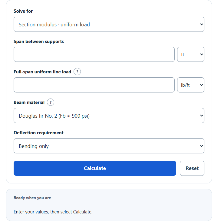
Calculate beam size for a simple span: enter span and load, pick wood, glulam, LVL or steel, and get the required section modulus or rectangular depth.
Related Calculators
- Load Per Square Foot Calculator
- Steel Deflection Calculator
- Pole Wind Load Calculator
- Bridge Weight Calculator
- All Construction Calculators
Calculator Functions
| Function | What it does | What it requires |
|---|---|---|
| Section modulus · uniform load | Finds the section modulus a simple-span beam needs to carry a load spread evenly along its full length | Requires the span between supports, the uniform line load and a beam material or allowable bending stress |
| Section modulus · center load | Finds the section modulus a simple-span beam needs to carry one point load at mid-span | Requires the span between supports, the point load and a beam material or allowable bending stress |
| Depth · uniform load | Finds the minimum depth of a rectangular beam of known width under a full-span uniform load | Requires the span, the uniform line load, a beam material or allowable bending stress, and the actual beam width |
| Depth · center load | Finds the minimum depth of a rectangular beam of known width under one point load at mid-span | Requires the span, the point load, a beam material or allowable bending stress, and the actual beam width |
Every function covers a single span resting on two supports. The Beam material list fills in a bending stress and stiffness for Douglas fir No. 2, glulam, LVL and two steel grades, and Custom Fb and E accepts any other values. Setting the Deflection requirement to Also check deflection adds a stiffness check against a limit such as L/360. Span can be entered in ft, in, m or mm, and loads in lb/ft, lb/in, kN/m, N/m, lb, kN or N.
Beam Size Formulas
| S | Required section modulus (in³) |
| M | Maximum bending moment (lb-in, which is lb-ft × 12) |
| Fb | Adjusted allowable bending stress (psi), not yield or ultimate strength |
The beam passes the bending check when its section modulus is at least S. The four functions differ only in how the moment is found and whether S is turned into a depth.
Section modulus · uniform load
w is the load per unit length over the whole span and L is the span. The largest moment is at mid-span. A 10 ft span carrying 1,000 lb/ft has M = 1,000 × 10² ÷ 8 = 12,500 lb-ft, and at Fb = 1,200 psi it needs S = 12,500 × 12 ÷ 1,200 = 125 in³. The uniform load should include the beam’s own weight when it is known.
Section modulus · center load
P is a single load at the middle of the span. A 5,000 lb load on a 10 ft span gives the same 12,500 lb-ft as the uniform example, because that uniform load totals 10,000 lb and a center load bends a beam twice as hard as the same weight spread out. This function models the point load alone and does not add the beam’s own weight.
Depth · uniform load
A solid rectangle of width b and depth d has S = b × d² ÷ 6, and this is that relation solved for d. With S = 125 in³ and an actual width of 3.5 in, d = √(6 × 125 ÷ 3.5) = 14.64 in. The width is the actual dimension, not the nominal lumber size: a nominal 4 in member is 3.5 in wide. The result is a minimum, to be rounded up to a section that is actually sold.
Depth · center load
The depth comes from the same rectangle relation, with S taken from the center-load moment P × L ÷ 4.
Deflection check
I = P × L² × r ÷ (48 × E)
With Also check deflection selected, the calculator also finds the second moment of area I that keeps mid-span deflection within L ÷ r, where r is the limit denominator (360 for L/360) and E is the modulus of elasticity. The first line is for a uniform load and the second for a center load. They come from the maximum deflections 5wL⁴ ÷ (384EI) and PL³ ÷ (48EI) [1], set equal to L ÷ r. The depth functions then use I = b × d³ ÷ 12 to get a second depth, d = ∛(12 × I ÷ b), and report the larger of the two along with which check governs.
For the 5,000 lb center load on 10 ft with E = 1,600,000 psi and L/360, I = 337.5 in⁴ and the deflection depth at 3.5 in wide is 10.50 in, so the 14.64 in bending depth governs.
Material values in the Beam material list
| Beam material | Fb (psi) | E (psi) |
|---|---|---|
| Douglas fir-larch No. 2 | 900 | 1,600,000 |
| Glulam 24F-V4 | 2,400 | 1,800,000 |
| LVL 2.0E | 2,600 | 2,000,000 |
| Steel A992 (Fy 50 ksi) | 33,000 | 29,000,000 |
| Steel A36 (Fy 36 ksi) | 24,000 | 29,000,000 |
The wood figures are reference values before any adjustment. Published lumber stresses are adjusted for size, moisture, duration of load and other conditions before they are used in design [2], so the stress that applies to a given beam can be higher or lower than the number in the list. The steel figures are 0.66 × Fy, an allowable-stress value for compact sections braced against sideways buckling. A steel beam is chosen by finding a shape whose listed section modulus is at least S, so the two section modulus functions are the ones to use for steel I-beams, and the depth functions apply only to solid rectangles such as sawn lumber, glulam and LVL.
How to Calculate Beam Size
Beam size follows from four numbers: the span, the load, the allowable bending stress of the material and, for a rectangular beam, its width. Find the maximum moment from the span and load (w × L² ÷ 8 for a uniform load, P × L ÷ 4 for a center load), convert it to lb-in, and divide by the allowable bending stress to get the required section modulus. For a rectangular beam, d = √(6 × S ÷ b) turns that into a depth. If a deflection limit applies, work out the required I as well and keep the larger depth. A beam sized this way has passed bending and deflection only, which is the starting point for a design and not the end of it.
Limits of This Estimate
- The result covers elastic bending and, when selected, deflection. It does not check shear, bearing at the supports, lateral stability, connections, combined loads, long-term creep or vibration. A qualified engineer should verify the final section and the load combinations.
- Only a single span on two simple supports is modeled, with either a full-span uniform load or one load at mid-span. Cantilevers, continuous beams, partial loads and off-center loads have different moments.
- The material list holds typical values, and a result that uses it is labeled an estimate. The grade stamp, the manufacturer’s literature and the governing code give the values for a specific beam. These estimates are based on the best available data and estimations.
- The same load is used for bending and for deflection. Building codes can require separate total-load and live-load deflection checks.
Sources
- American Wood Council, Design Aid No. 6, Beam Design Formulas with Shear and Moment Diagrams, Figures 1 and 7: maximum moment and deflection of a simple beam under a uniform load and under a load at the center
- USDA Forest Products Laboratory, Wood Handbook (FPL-GTR-282), Chapter 7: how lumber properties are adjusted for size, moisture and duration of load to give design stresses