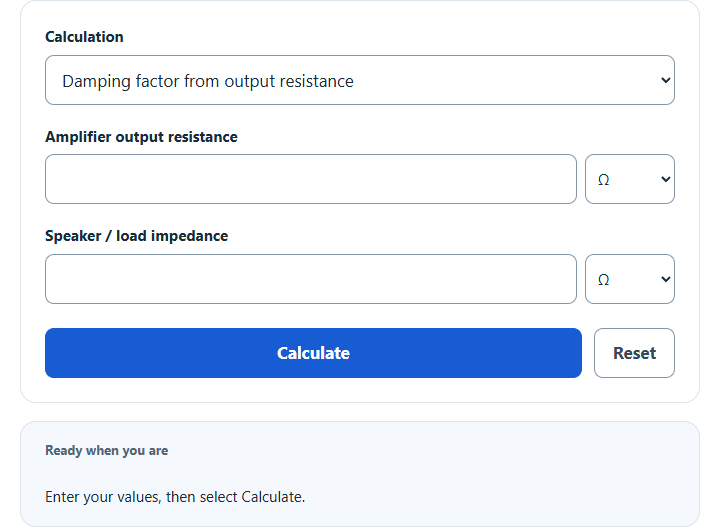
Calculate audio damping factor from amplifier output resistance and load impedance, or estimate system damping factor with speaker cable effects.
Calculator Functions
| Function | What it does | What it requires |
|---|---|---|
| Damping factor from output resistance | Finds the damping factor of an amplifier driving a load | Requires the amplifier output resistance and the speaker or load impedance |
| Output resistance from damping factor | Finds the amplifier output resistance behind a damping factor | Requires the speaker or load impedance and the damping factor |
| Load impedance from damping factor | Finds the load impedance that gives a damping factor | Requires the amplifier output resistance and the damping factor |
| System damping factor with speaker cable | Estimates the damping factor at the speaker once cable resistance is added | Requires the speaker nominal impedance, the amplifier damping factor and its reference load, the one-way cable length, the gauge and the cable material |
Resistance and impedance can be entered in Ω, kΩ or MΩ, with 4, 6, 8 and 16 Ω offered as load presets. Every result also carries a band label: above 100 is very high, above 50 high, above 15 moderate, above 10 low to moderate, and anything else low. The bands only describe the size of the number.
Damping Factor Formulas
| DF | Damping factor (no unit) |
| Z | Speaker or load impedance (Ω) |
| R | Amplifier output resistance (Ω) |
Damping factor from output resistance
The formula above applies directly. An amplifier with 0.08 Ω of output resistance driving an 8 Ω speaker has a damping factor of 8 ÷ 0.08 = 100 [1].
Output resistance from damping factor
Amplifier specifications usually state damping factor against an 8 Ω load, so a rated damping factor of 370 means 8 ÷ 370 = 0.0216 Ω of output resistance [1].
Load impedance from damping factor
An output resistance of 0.05 Ω reaches a damping factor of 160 into 160 × 0.05 = 8 Ω.
System damping factor with speaker cable
The cable sits in series with the amplifier, so its resistance adds to the output resistance [1] [2]. Ramp is the reference load divided by the amplifier damping factor. Rcable is 2 × the one-way length in feet × the resistance per foot, because the current flows out and back [2]. A length in meters is divided by 0.3048 first.
| Gauge | Copper, Ω per foot at 20 °C |
|---|---|
| 10 AWG | 0.0010 |
| 12 AWG | 0.001588 |
| 14 AWG | 0.002525 |
| 16 AWG | 0.004016 |
| 18 AWG | 0.006385 |
These are the values for solid annealed copper [3]. For copper-clad aluminum the calculator multiplies them by 1.47. An amplifier rated at a damping factor of 300 into 8 Ω has 0.0267 Ω of output resistance. Twenty feet of 12 AWG copper adds 2 × 20 × 0.001588 = 0.0635 Ω, so an 8 Ω speaker sees 8 ÷ 0.0902 = 88.7.
Limits of This Estimate
- Speaker impedance and amplifier output impedance both change with frequency, so the damping factor does too [1] [2]. The calculator works with one resistance and one impedance value at a time.
- A higher damping factor is not a rating of sound quality [2].
- Cable values are for solid copper at 20 °C [3]. Stranded cable, warmer cable, connectors and the crossover inside the speaker add resistance that is not counted.
- The 1.47 factor for copper-clad aluminum is a rule of thumb, and real cable varies with its copper content. These estimates are based on the best available data and estimations.
Sources
- Benchmark Media Systems, Audio Myth: Damping Factor Isn’t Much of a Factor: damping factor as speaker impedance over amplifier output impedance, the 8 Ω reference and cable resistance
- KEF, Damping Factor Explained: system damping factor with amplifier and cable impedance together
- National Bureau of Standards Handbook 100, Copper Wire Tables: resistance of copper wire by gauge at 20 °C