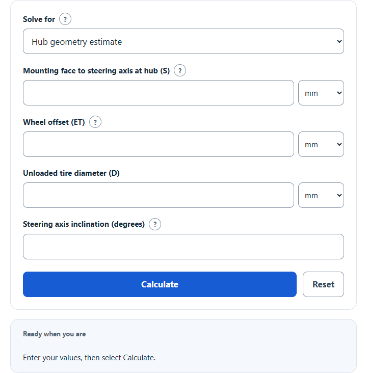
Calculate scrub radius from hub geometry (offset, tire size and SAI) or measured ground points, or find how a new wheel offset or spacer changes it.
Related Calculators
- Braking Torque Calculator
- Kingpin-to-Rear-Axle (KPRA) Calculator
- Tire Rollout Calculator
- Shock Force Calculator
- Wheel Force Calculator
- All Automotive Calculators
Scrub Radius Formula
The measured-coordinate definition is shown below. With outboard positive, the simplified hub model is SR = S − ET − (D ÷ 2) × tan(SAI). Here S is the mounting-face outboard distance from the steering axis at hub height; positive ET places the mounting face outboard of wheel center, and positive SAI leans inboard upward. Angles are in degrees, strictly between −90° and 90°.
Scrub radius = contact-patch center position − steering-axis ground-intersection position.
Variables (all measured at the road surface, using the same reference and sign convention):
- SR is the scrub radius (mm or in)
- xCP is the lateral position of the center of the tire contact patch (mm or in)
- xSA is the lateral position of the steering-axis (kingpin) intersection with the ground (mm or in)
In other words, scrub radius is the lateral distance from the steering-axis ground intersection to the tire contact patch center. This calculator uses a common sign convention where SR is positive if the contact patch center is outboard of the steering-axis ground intersection, and negative if it is inboard.
What is a Scrub Radius?
Scrub radius is an important aspect of a vehicle’s steering geometry and affects steering feel, stability under braking, and sensitivity to road disturbances. A positive scrub radius occurs (using the convention on this page) when the steering-axis intersection with the ground lies inboard of the center of the tire contact patch. A negative scrub radius occurs when the steering-axis intersection lies outboard of the contact patch center. Zero scrub radius is when the two points coincide.
How to Calculate Scrub Radius?
Choose Hub geometry estimate, Change from offset or spacer, or Measured ground coordinates. Hub geometry omits actual loaded radius, nonzero camber, suspension travel, ride-height changes and tire deflection. For unchanged tire/suspension geometry, change in SR = original ET − new ET + newly added spacer thickness; blank spacer thickness means zero. This gives a change, not the new absolute scrub radius or its sign.
- For Measured ground coordinates, determine the steering-axis ground intersection (xSA) from measurements or suspension geometry at the vehicle’s relevant load and ride height. Use one lateral reference and an outboard-positive axis for both positions.
- Determine the tire contact-patch center (xCP) at the road surface in that same measurement state. The hub estimate approximates this point from wheel-center position only under its zero-camber assumption.
- Use the formula from above: SR = xCP − xSA.
- Select Calculate. Each length field accepts millimeters or inches and converts units without reinterpreting the value; results are shown in millimeters with inches alongside.
- Review the signed result and expandable details. A zero offset/spacer change is unchanged, rather than more positive. Check actual geometry and permissible modifications using the vehicle manufacturer’s current procedures and limits.
Example Problem:
Use the following variables as an example problem to test your knowledge (inboard = −, outboard = +):
steering-axis ground intersection position (xSA) = −100 mm
tire contact patch center position (xCP) = −40 mm
Select Measured ground coordinates and enter these values. Then SR = (−40) − (−100) = 60 mm (positive); the contact-patch center is 60 mm outboard of the steering-axis ground intersection.