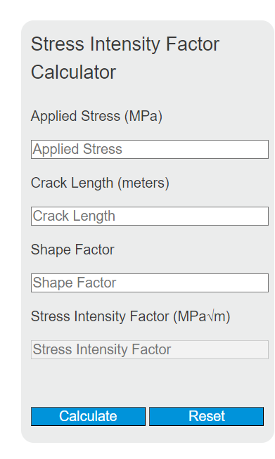
Calculate stress intensity factor K from applied stress and crack length for center, edge, or custom crack geometry with shape factor Y.
Related Calculators
- Plastic Modulus Calculator
- Concrete Shear Capacity Calculator
- Safe Working Load Calculator
- Steel Shrinkage Calculator
- All Construction Calculators
Stress Intensity Factor Formula
The stress intensity factor measures the severity of the stress field at the tip of a crack. In linear-elastic fracture mechanics, it is commonly used to estimate whether an existing flaw is likely to remain stable or continue growing under load. This calculator uses the standard geometry-corrected expression for an opening crack.
| Symbol | Meaning | Typical units | Practical note |
|---|---|---|---|
| K | Stress intensity factor | MPa√m, psi√in, or kpsi√in | The calculator output you compare against allowable fracture resistance. |
| σ | Applied stress | MPa, kPa, or psi | Higher applied stress increases the crack-tip driving force directly. |
| a | Crack length used by the chosen geometry | m, cm, in, or ft | Use the crack definition that matches your shape factor and crack model. |
| Y | Shape factor | Dimensionless | Accounts for part geometry, crack location, and crack shape. |
A larger result means a more severe crack-tip condition. The value increases in direct proportion to applied stress and shape factor, while crack length affects the result through a square-root relationship. That means longer cracks matter a lot, but not in a simple one-to-one way.
How to Calculate Stress Intensity Factor
- Enter the applied stress in a consistent stress unit.
- Enter the crack length in a consistent length unit.
- Enter the shape factor for the crack geometry being analyzed.
- Multiply the applied stress by the square root of pi times the crack length.
- Multiply that intermediate value by the shape factor to obtain the stress intensity factor.
Example Calculation
If the applied stress is 75 MPa, the crack length is 0.05 m, and the shape factor is 1.12, the substitution is:
This gives:
How Each Input Changes the Result
| Input change | Effect on result | Why it matters |
|---|---|---|
| Applied stress doubles | Stress intensity factor doubles | The relationship with stress is linear. |
| Shape factor doubles | Stress intensity factor doubles | The geometry correction acts as a direct multiplier. |
| Crack length doubles | Stress intensity factor increases by about 41% | Crack length enters through a square root, not a linear term. |
| Crack length quadruples | Stress intensity factor doubles | Square-root scaling makes large crack growth especially important. |
How to Interpret the Result
The calculator gives the crack-tip loading severity for the inputs you provide. In practice, engineers often compare that value with the material’s fracture toughness for the same loading mode, temperature, thickness, and condition.
When the calculated stress intensity factor remains well below the applicable fracture toughness, the crack is less likely to experience unstable fracture under the stated conditions. If the calculated value approaches or exceeds the critical toughness, the risk of rapid crack extension increases.
Assumptions Behind This Equation
- Linear-elastic behavior: the material response is assumed to remain predominantly elastic near the crack.
- Sharp crack: the flaw is treated as a crack rather than a blunt notch.
- Correct geometry factor: the shape factor must match the component and crack configuration.
- Mode consistency: this form is typically used for opening-mode crack analysis.
- Small-scale yielding: local plasticity is assumed to be limited enough for linear-elastic fracture mechanics to remain useful.
Common Mistakes
- Using the wrong crack length definition: some crack formulas use total crack length, while others use half-length or crack depth.
- Choosing an incorrect shape factor: edge cracks, center cracks, surface cracks, and holes with cracks do not share the same correction factor.
- Mixing units manually: stress and crack length units must be compatible with the desired output units.
- Ignoring loading mode: fracture toughness and stress intensity factors should be compared only when the mode and conditions align.
- Treating the result as a full failure analysis: crack growth rate, cyclic loading, residual stress, temperature, and material variability can all matter.
Unit Guidance
| Stress input | Length input | Typical output form |
|---|---|---|
| MPa | m | MPa√m |
| psi | in | psi√in or kpsi√in |
| kPa | m | kPa√m |
For the most reliable result, use the same unit system all the way through and verify that the output unit matches the property you plan to compare against.
Quick Answers
- What does the shape factor represent?
- It adjusts the ideal crack solution for real geometry effects such as crack position, crack shape, specimen width, and boundary conditions.
- Why does crack length matter so much?
- Even when nominal stress stays the same, a longer crack intensifies the local stress field at the crack tip and makes further growth more likely.
- Is a higher stress intensity factor always bad?
- A higher value indicates a more severe crack-tip condition. Whether it is acceptable depends on the material’s fracture resistance and the actual service conditions.
- Can this calculator replace a detailed fracture assessment?
- No. It is best used for quick estimation, screening, and understanding trends. Critical applications may require full fracture mechanics review, inspection data, and material-specific toughness values.