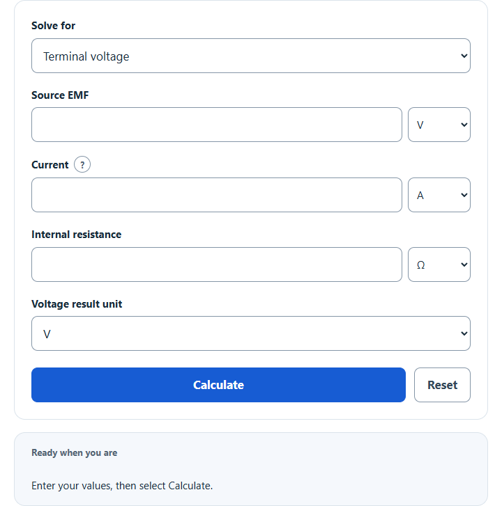
Calculate the terminal voltage of a battery or cell from its EMF, current and internal resistance (V = E − I×r), or solve for EMF, current or r.
Terminal Voltage Formula
Terminal voltage is the actual voltage available at the terminals of a battery, cell, or source while current is flowing. In real sources, the terminal voltage is usually lower than the ideal EMF because some voltage is lost inside the source due to internal resistance.
For a source delivering power to a load, this equation gives the usable output voltage seen at the terminals.
| Symbol | Description | Common Unit |
|---|---|---|
| Vt | Terminal voltage | volts (V) |
| E | Total EMF or ideal source voltage | volts (V) |
| I | Current supplied by the source | amps (A) |
| R | Internal resistance of the source | ohms (Ω) |
Rearranged Forms
Because the calculator can solve for any missing value, the terminal voltage equation is often rearranged as follows:
How to Use the Calculator
- Select the value to solve for, then enter the three known quantities.
- Select matching units for voltage, current, and resistance.
- Use internal resistance, not the external load resistance.
- Calculate to find the missing variable.
Match each value to its selected unit; input unit changes convert the current quantity. In Vt = E − Ir, positive current leaves the source’s positive terminal; negative current represents charging and can make terminal voltage exceed EMF. Internal resistance is nonnegative. Zero denominators that prevent a unique inverse are reported.
How to Interpret the Result
| Condition | What Happens to Terminal Voltage |
|---|---|
| No current flow | Terminal voltage matches the EMF because there is no internal voltage drop. |
| Higher positive discharge current, at fixed EMF and internal resistance | Terminal voltage decreases because the internal drop becomes larger. |
| Higher internal resistance, at fixed EMF and positive discharge current | Terminal voltage decreases more sharply under load. |
| Better source condition | Lower internal resistance helps the source maintain a voltage closer to its EMF. |
Example 1
A source has an EMF of 24 V, delivers 4 A, and has an internal resistance of 0.75 Ω.
The source provides 21 V at its terminals while operating under load.
Example 2
A source has an EMF of 9 V, a terminal voltage of 8.4 V, and a current of 1.5 A. Find the internal resistance.
This means the source loses 0.6 V internally at that operating current.
Common Mistakes
- Using load resistance instead of internal resistance.
- Mixing units such as mA, A, kΩ, and Ω without converting properly.
- Assuming terminal voltage is always the same as EMF.
- Ignoring the effect of increased current draw on source performance.
Where Terminal Voltage Matters
- Batteries: shows how much voltage is actually available when powering a device.
- Power supplies: helps evaluate voltage sag under load.
- Electrical testing: useful for estimating internal resistance and source health.
- Circuit design: helps ensure connected components receive the voltage they require.
In practice, terminal voltage is one of the clearest indicators of how a real source behaves under load. A large drop from EMF to terminal voltage usually points to high current demand, significant internal resistance, or both.