Calculate microstrip impedance, guided wavelength, losses, and electrical length, or find R, L, C, and Z0 for twin, coax, and parallel lines.
Related Calculators
- 3 Phase Voltage Calculator
- Received Power Calculator
- Peak Envelope Power (PEP) Calculator
- Series Current Calculator
- All Physics Calculators
Transmission Line Formula
The characteristic impedance of a uniform transmission line is determined by its distributed primary constants: series resistance, series inductance, shunt conductance, and shunt capacitance. This is the impedance a forward-traveling wave “sees” as it propagates down the line, and it is the terminating impedance that eliminates reflections on a matched line.
In this expression:
| Symbol | Meaning | Typical Unit | Physical Interpretation |
|---|---|---|---|
| Z0 | Characteristic impedance | Ω | The natural impedance of the line for a traveling wave |
| R | Resistance per unit length | Ω/m or Ω/ft | Conductor loss |
| L | Inductance per unit length | H/m or H/ft | Magnetic energy storage along the line |
| G | Conductance per unit length | S/m or S/ft | Leakage through the dielectric |
| C | Capacitance per unit length | F/m or F/ft | Electric energy storage between conductors |
| ω | Angular frequency | rad/s | Signal frequency in angular form |
| j | Imaginary unit | — | Represents phase-sensitive reactive behavior |
Useful Simplifications
For many practical lines, the losses are small compared with the reactive terms. In that low-loss case, the characteristic impedance is often approximated by the square root of the inductance-to-capacitance ratio.
If the line is treated as perfectly lossless, this same relation becomes exact.
If your known signal frequency is given in hertz rather than radians per second, convert it before using the full equation.
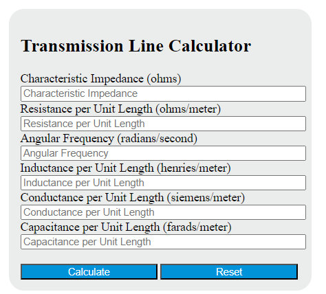
How to Use the Transmission Line Calculator
- Enter five known values from the set of line parameters and the calculator will solve for the missing one.
- Keep all per-length quantities in the same length basis. If one value is per foot, the others must also be per foot.
- Use angular frequency in rad/s, not ordinary frequency in hertz unless you convert it first.
- Check that the units are realistic for the type of line you are analyzing, such as cable, twisted pair, PCB trace, or waveguide equivalent model.
- Interpret the answer as the line’s intrinsic impedance, not the total DC resistance of the conductor.
What the Result Means
- When the load equals the characteristic impedance, reflections are minimized and power transfer along the line is most efficient.
- When the load does not equal the characteristic impedance, part of the wave reflects back toward the source.
- When losses are very small, the characteristic impedance is usually close to a real number and is often treated as a nominal value such as 50 Ω, 75 Ω, or 100 Ω in design work.
- When losses are significant, the characteristic impedance can be complex, meaning both magnitude and phase matter.
Example
Suppose a low-loss line has an inductance per unit length of 2.5 × 10⁻⁷ H/m and a capacitance per unit length of 1.0 × 10⁻¹⁰ F/m. With conductor and dielectric losses small enough to ignore, the characteristic impedance is:
This means the line should ideally be terminated with 50 Ω to avoid reflections.
Why Line Length Is Not in the Formula
Characteristic impedance is a property of the line’s geometry and materials, captured through the distributed parameters per unit length. Total length affects other behavior, including attenuation, phase shift, and propagation delay, but it does not change the nominal characteristic impedance of a uniform line.
Related Transmission-Line Quantities
If you are analyzing more than matching alone, two other quantities are especially useful: the propagation constant and the reflection coefficient.
These relationships help explain why matching matters: once the load impedance differs from the line impedance, reflected energy appears, standing waves increase, and signal integrity can degrade.
Practical Notes
- Do not confuse characteristic impedance with resistance. A line can have a 50 Ω characteristic impedance without having 50 Ω of end-to-end DC resistance.
- Keep unit systems consistent. Mixing per-meter and per-foot values will produce a wrong answer.
- Use the full formula for lossy or frequency-sensitive analysis. The simplified form is best when resistance and leakage are small.
- Fast digital edges can behave like high-frequency signals. Even when the clock rate seems moderate, long interconnects may still need transmission-line treatment.
- Matching is application-dependent. RF systems usually target a specific nominal impedance, while high-speed digital links focus on controlling reflections and preserving waveform shape.
Common Input Mistakes
- Entering frequency in Hz when the calculator expects angular frequency
- Using total resistance instead of resistance per unit length
- Mixing unit bases such as H/m with F/ft
- Assuming a longer cable automatically changes the characteristic impedance
- Ignoring dielectric leakage in cases where the insulation is not ideal