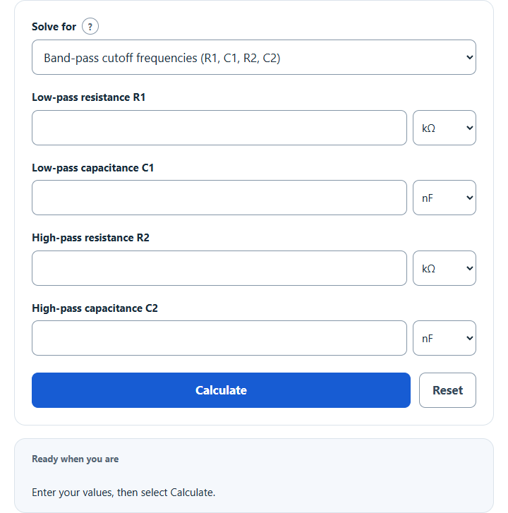
Calculate RC band-pass filter cutoff frequencies, center frequency and bandwidth from R and C, find a single low-pass or high-pass cutoff, or size R or C.
Bandpass Filter Formula
The following formulas calculate the individual corner frequencies of first-order high-pass and low-pass RC stages. They assume buffering or negligible loading between stages. These stage corners are not generally the complete cascade’s −3 dB edges relative to its peak.
- Where LCF is the lower cutoff frequency (Hz)
- HCF is the high cutoff frequency (Hz)
- R1 and R2 are the resistances in a passive RC bandpass filter
- C1 and C2 are the capacitances in a passive RC bandpass filter
Band-Stop: Passive Twin-T Notch
The secondary twin-T modes calculate notch frequency f₀ = 1/(2πRC), or solve R or C for a target f₀. This is a different circuit from the band-pass stages: connect an R–2C–R T-network and a C–(R/2)–C T-network in parallel, with their shunt elements grounded. The output lists all six component values. For R = 10 kΩ and C = 100 nF, f₀ is about 159.1549 Hz; the shunt values are 5 kΩ and 200 nF.
For matched ideal components, negligible source resistance and an unloaded output, the passive twin-T has Q = 0.25. Its unity-passband −3 dB edges are f₀(√5 − 2) and f₀(√5 + 2), with bandwidth 4f₀. These are model-specific edges, not generic edges of arbitrary parallel RC stages. Component mismatch and loading change the response; verify the complete design. See Analog Devices MT-225 for the twin-T equations and component ratios.
What is a Bandpass Filter?
A Bandpass Filter is an electronic circuit that allows a specific range of frequencies to pass through while attenuating or blocking frequencies outside of this range. It combines the properties of two other filters: the low-pass filter, which allows low-frequency signals to pass through, and the high-pass filter, which allows high-frequency signals to pass through.
The importance of a Bandpass Filter lies in its ability to selectively filter out unwanted frequencies and isolate the desired frequency range. By doing so, it enhances the clarity and quality of signals in various applications.
For instance, in audio systems, a Bandpass Filter can eliminate noise and interference, ensuring that only the desired range of frequencies, such as vocals or instruments, is reproduced. This results in improved sound fidelity and a better listening experience.
Bandpass Filters are also crucial in communication systems. They enable the transmission and reception of signals within specific frequency bands, allowing for efficient utilization of available bandwidth.
By blocking out unwanted frequencies, they help to reduce interference from other signals, enhancing the reliability and accuracy of data transmission. This is particularly important in wireless communication, where multiple devices operate simultaneously within the same spectrum.
Example Problem
How to calculate the cutoff frequencies of a bandpass filter?
First, determine the resistance and capacitance of C1 and R1. R1 and C1 denote the low-pass stage; R2 and C2 denote the high-pass stage.
For this example, the first capacitance and resistance are 5 farads and 2 ohms respectively. Keep in mind these may not be realistic for real-world bandpass filters but can be used to show the calculations more simply.
Next, determine the second capacitance and resistance. In this case, these values are found to be 10 farads and 4 ohms respectively.
Finally, select Band-pass cutoff frequencies (R1, C1, R2, C2) and Calculate to find the nominal lower and upper stage corners.
LCF = 1/(2*pi*R2*C2)
= 1/(2*3.14159*4*10)
= 0.00398 Hz
HCF = 1/(2*pi*R1*C1)
= 1/(2*3.14159*2*5)
= 0.0159 Hz.
FAQ
What are the components of a bandpass filter?
An RC bandpass filter typically consists of resistors and capacitors. The resistors (R1 and R2) and capacitors (C1 and C2) work together to define the lower and upper cutoff frequencies of the filter, allowing it to pass a specific range of frequencies while blocking others.
How do cutoff frequencies affect a bandpass filter's performance?
The complete filter’s −3 dB edges are conventionally measured relative to peak gain. Attenuation changes gradually rather than abruptly. Stage corner frequencies alone do not specify the full response; loading and the spacing of the corners matter. For measured edges fL and fU, bandwidth = fU − fL, geometric center = √(fL × fU), and Q = center / bandwidth.
Can bandpass filters be used in digital signal processing?
Yes, bandpass filters are not only used in analog circuits but also in digital signal processing (DSP). In DSP, they are implemented through algorithms to process digital signals, allowing specific frequency components to be isolated or removed according to the filter's design.
Why are bandpass filters important in communication systems?
Bandpass filters play a crucial role in communication systems by enabling the transmission and reception of signals within specific frequency bands. This helps in efficient bandwidth utilization and reduces interference from other signals, thereby enhancing the reliability and quality of data transmission in both wired and wireless communication systems.