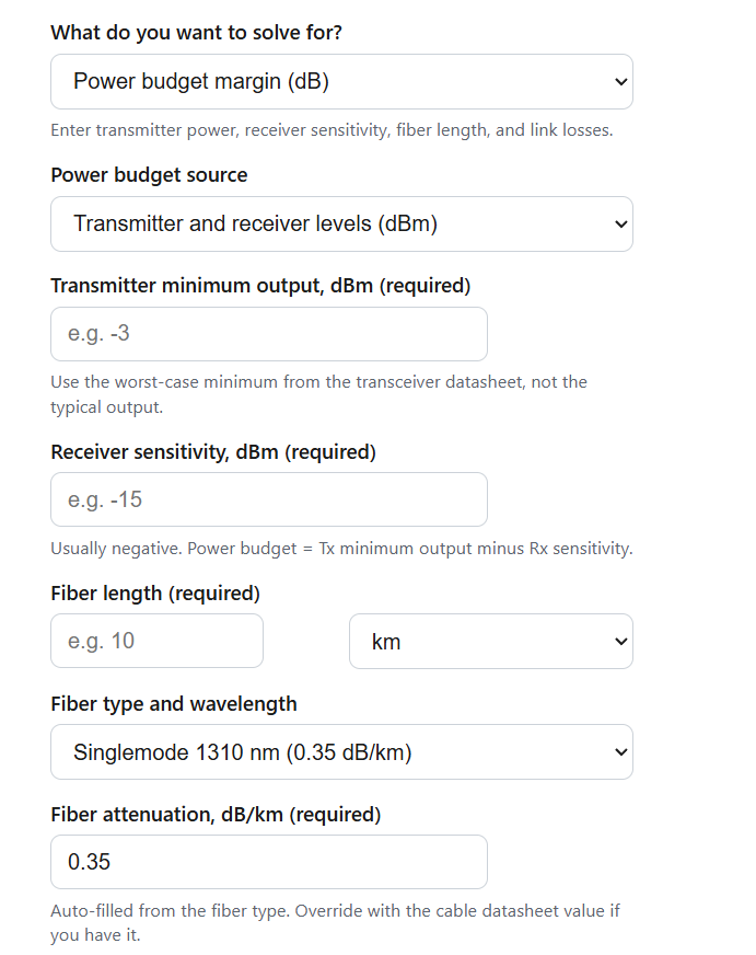
Calculate the power budget margin of a fiber optic link from transmitter power, receiver sensitivity, and fiber, connector, splice, and splitter losses.
Fiber Optic Power Budget Margin Formula
PB = Tx - Rx
TL = (L * a) + (Nc * Cc) + (Ns * Cs) + Lsp + Lo
M = PB - TL
Dmax = (PB - Md - Lfixed) / a
- PB is the power budget (dB)
- Tx is the transmitter minimum output power (dBm)
- Rx is the receiver sensitivity (dBm)
- TL is the total link loss (dB)
- L is the fiber length (km) and a is the fiber attenuation (dB/km)
- Nc is the number of mated connector pairs and Cc is the loss per pair (dB)
- Ns is the number of splices and Cs is the loss per splice (dB)
- Lsp is the splitter loss (dB) and Lo is any other passive loss (dB)
- M is the power budget margin (dB)
- Dmax is the maximum fiber distance (km), Md is the design safety margin (dB), and Lfixed is the sum of all non-fiber losses (dB)
The margin mode applies the first three formulas in order. The power budget comes either from the transmitter and receiver levels, where the difference of two dBm values gives a relative budget in dB, or from a budget you already know. The calculator then sums fiber, connector, splice, splitter, and other losses into the total link loss and subtracts it from the budget to return the margin. When you enter transmitter and receiver levels, it also reports the expected receive power in dBm.
The maximum distance mode rearranges the same relationship. It removes the fixed losses and the design safety margin from the budget, then divides what remains by the attenuation per kilometer to find the longest fiber run the budget supports. The required power budget mode works in reverse: it adds your total link loss to the design margin to tell you the budget your optics must supply, and if you enter a receiver sensitivity it converts that into the minimum transmitter power in dBm.
Standard Loss Values and What Your Margin Means
Use these component values when you do not have datasheet numbers. Typical values reflect good field workmanship, while the standard maximums are the screening limits used in TIA-568 style loss budgets.
| Component | Typical value | Standard maximum |
|---|---|---|
| Singlemode fiber, 1310 nm | 0.35 dB/km | 0.5 dB/km |
| Singlemode fiber, 1550 nm | 0.25 dB/km | 0.5 dB/km |
| Multimode fiber, 850 nm | 3.0 dB/km | 3.5 dB/km |
| Multimode fiber, 1300 nm | 1.0 dB/km | 1.5 dB/km |
| Mated connector pair | 0.3 dB | 0.75 dB |
| Fusion splice | 0.05 to 0.1 dB | 0.3 dB |
| PON splitter 1:8 | 10.5 dB | 10.7 dB |
| PON splitter 1:32 | 17.1 dB | 17.7 dB |
The margin number only becomes useful once you translate it into action. The table below interprets the result against the common 3 dB design reserve and shows what each band is worth in extra singlemode fiber at 1310 nm, a conversion competing references rarely provide. Because singlemode loses about 0.35 dB/km, every decibel of spare margin is roughly 2.9 km of future route flexibility.
| Margin result | Interpretation | Recommended action |
|---|---|---|
| Below 0 dB | Link fails on paper before it is built | Shorten the route, cut connector count, use lower-loss fiber, or pick higher-power optics |
| 0 to 3 dB | Works on day one but has no reserve for aging or repair splices | Treat as failing for new designs; acceptable only as a documented exception |
| 3 to 6 dB | Meets the standard 3 dB reserve; roughly 0 to 8 km of spare singlemode reach | Approve the design and record the margin for maintenance baselines |
| 6 to 10 dB | Healthy reserve; roughly 8 to 20 km of spare singlemode reach | Good target for links that may be extended or re-spliced later |
| Above 10 dB | More power than the link needs, common on short singlemode jumpers | Check the receiver maximum input; add an inline attenuator if receive power exceeds it |
Fiber Optic Power Budget Margin Example Problems
Example 1: A 10 km singlemode campus link at 1310 nm uses a transceiver with a minimum output of -5 dBm and a receiver sensitivity of -20 dBm. The run has 3 mated connector pairs at 0.5 dB each and 6 fusion splices at 0.1 dB each. The power budget is -5 – (-20) = 15 dB. The total link loss is (10 * 0.35) + (3 * 0.5) + (6 * 0.1) = 3.5 + 1.5 + 0.6 = 5.6 dB. The margin is 15 – 5.6 = 9.4 dB, a healthy result. With a 3 dB reserve held back, the spare 6.4 dB equals about 18.3 km of additional fiber headroom.
Example 2: A GPON design has an OLT transmit power of +2 dBm and an ONT sensitivity of -28 dBm, giving a 30 dB budget. The path includes a 1:32 splitter at 17.7 dB, 2 connector pairs at 0.5 dB each, and 4 splices at 0.1 dB each, so the fixed losses total 17.7 + 1.0 + 0.4 = 19.1 dB. At zero margin the maximum distance is (30 – 19.1) / 0.35 = 31.14 km. Reserving a 3 dB design margin, the maximum drops to (30 – 3 – 19.1) / 0.35 = 22.57 km, which is why 1:32 GPON deployments are commonly planned around a 20 km reach.
Fiber Optic Power Budget Margin FAQs
What is a good power budget margin? A margin of at least 3 dB above zero is the common design target. The reserve absorbs connector wear, added repair splices, temperature effects, and the slow drop in laser output as a transmitter ages. Some carrier and outside-plant specifications call for 5 dB or more, so use the value in your project specification when one exists.
What is the difference between the power budget, the loss budget, and the margin? The power budget belongs to the electronics: transmitter minimum output minus receiver sensitivity. The loss budget belongs to the cable plant: the sum of fiber, connector, splice, and splitter losses you expect the installed link to show. The margin is the difference between the two, and it is the single number that says whether the design has room to operate reliably.
Can the margin be too high? Yes. On a short singlemode link with a powerful transmitter, so little light is lost that the receive power can exceed the receiver maximum input, which causes errors or damage. If your margin is far above 10 dB on a short run, compare the expected receive power against the receiver overload rating and add a fixed inline attenuator to bring the level into range.