Calculate heat exchanger area, heat duty, overall heat transfer coefficient or ΔTlm from any three inputs in BTU/h, kW, MW, °F, °C, ft² or m².
- All Physics Calculators
- All Area Calculators
- Coaxial Heat Exchanger Calculator
- Heat Exchanger Effectiveness Calculator
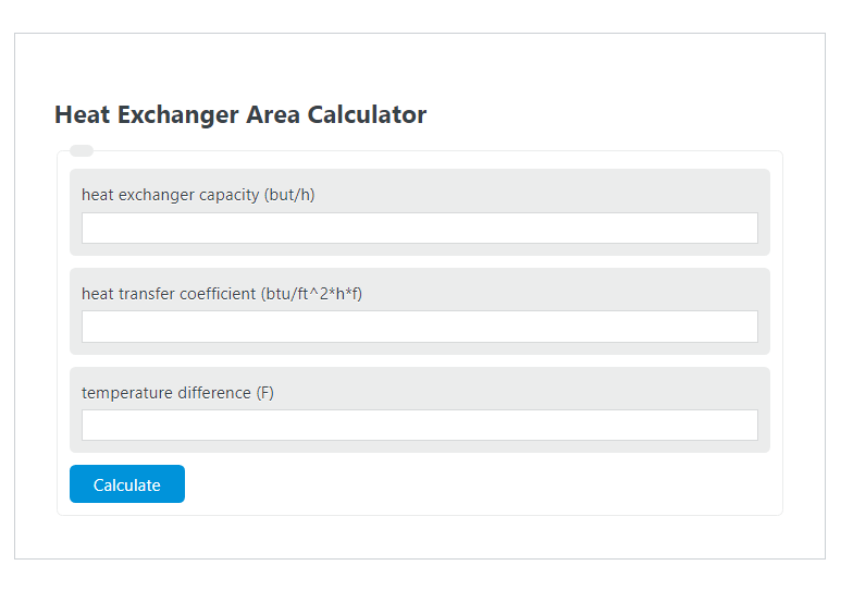
How to Use the Heat Exchanger Area Calculator
This calculator rearranges the standard heat-transfer sizing equation so you can solve for the missing variable when the other three are known. It is useful for quick exchanger sizing, validating design assumptions, and checking how changes in heat duty, heat transfer coefficient, or temperature difference affect the required surface area. The calculator is also set up to work with both Imperial and metric-style unit selections.
Core Heat Exchanger Area Formula
Where A is the required heat-transfer area, C is the heat duty or exchanger capacity, U is the overall heat transfer coefficient, and ΔT is the effective temperature driving force. Some references write the heat duty as Q, and some simplified calculators describe the coefficient as k instead of U.
What Each Input Means
- Heat duty / capacity (C): the amount of heat that must be transferred per unit time.
- Overall heat transfer coefficient (U): a combined measure of how easily heat moves from one fluid, through the wall, to the other fluid. It is affected by convection on both sides, wall conductivity, and fouling.
- Temperature difference (ΔT): the thermal driving force between the hot and cold streams.
- Area (A): the actual heat-transfer surface area required to move the target heat load.
How to Enter Values Correctly
- Determine the required heat duty from the process load.
- Select a realistic heat transfer coefficient based on the fluid pair, material, flow regime, and expected cleanliness.
- Use a representative temperature difference for the exchanger.
- Enter any three known values and solve for the fourth.
- If your design is still conceptual, add margin afterward for fouling, uncertainty, or future operating changes.
When a Simple Temperature Difference Is Not Enough
In real exchangers, the temperature difference usually changes from one end of the unit to the other. When you know the inlet and outlet temperatures of both streams, the more realistic driving force is the log mean temperature difference, commonly called LMTD. In that case, substitute ΔTlm for ΔT in the area equation.
Consistent Unit Pairings
| Heat Duty | Heat Transfer Coefficient | Temperature Difference | Area Result |
|---|---|---|---|
| BTU/h | BTU/ft²·h·°F | °F | ft² |
| W | W/m²·K | K | m² |
| kW or MW | W/m²·K | °C or K difference | m² after consistent conversion, or by using the calculator’s unit controls |
The most common input error is mixing systems, such as pairing BTU/h with W/m²·K. Keep every variable in one unit system unless the calculator is explicitly handling the conversion for you.
Fast Sensitivity Checks
| Change | Effect on Required Area |
|---|---|
| Capacity doubles | Area doubles if U and ΔT stay the same |
| U doubles | Area is cut in half if capacity and ΔT stay the same |
| ΔT doubles | Area is cut in half if capacity and U stay the same |
| Fouling increases | Effective U drops, so required area increases |
Examples
If the exchanger must transfer 120000 BTU/h, the overall heat transfer coefficient is 60 BTU/ft²·h·°F, and the temperature difference is 25°F:
If the exchanger must transfer 75 kW and the overall heat transfer coefficient is 500 W/m²·K with a 15°C temperature difference, first express 75 kW as 75000 W:
Common Mistakes to Avoid
- Using the wrong temperature difference: a single end-point difference can understate or overstate the real driving force.
- Ignoring fouling: a clean coefficient can make the calculated area too small for real service.
- Mixing units: inconsistent unit entry is one of the fastest ways to get a meaningless answer.
- Confusing area with footprint: calculated area is thermal surface area, not floor space, shell size, or exterior envelope.
Practical Interpretation
A small required area usually means you have either a strong temperature driving force, a high heat transfer coefficient, or a modest heat load. A large required area usually points to a small temperature difference, a low coefficient, significant fouling resistance, or a large required duty. That makes this calculator especially useful for comparing design tradeoffs before moving into detailed exchanger selection.