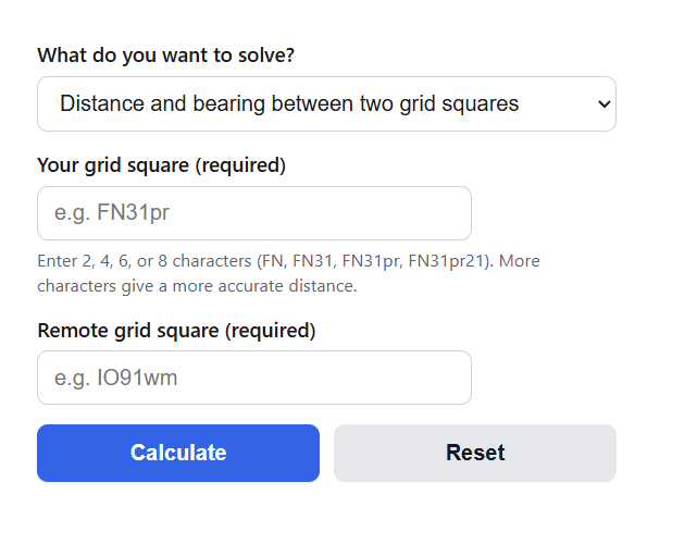
Calculate great-circle distance and beam heading between two Maidenhead grid squares, plus long path, back bearing, and grid to latitude-longitude conversion.
Maidenhead Grid Distance & Bearing Formula
The calculator first decodes each Maidenhead locator into the latitude and longitude of its square center. A field (2 characters) spans 10° of latitude by 20° of longitude, a square (4 characters) spans 1° by 2°, a subsquare (6 characters) spans 2.5 minutes by 5 minutes, and an extended square (8 characters) spans 15 seconds by 30 seconds. With both centers known, the short-path distance comes from the haversine formula:
d = 2 * R * asin( sqrt( sin^2((lat2 - lat1)/2) + cos(lat1) * cos(lat2) * sin^2((lon2 - lon1)/2) ) )
The initial bearing, which is the beam heading you rotate your antenna to, comes from:
brg = atan2( sin(lon2 - lon1) * cos(lat2) , cos(lat1) * sin(lat2) - sin(lat1) * cos(lat2) * cos(lon2 - lon1) )
The long-path results go the opposite way around the globe:
d_long = 2 * pi * R - d ; brg_long = (brg + 180) mod 360
Variables:
- d is the short-path (great circle) distance in kilometers
- R is the Earth mean radius, 6371.0088 km
- lat1, lon1 and lat2, lon2 are the coordinates of the two square centers in radians, with north latitude and east longitude positive
- brg is the initial bearing from station 1 to station 2 in degrees, measured clockwise from true north
- d_long and brg_long are the long-path distance and bearing
The default mode applies all three formulas between two locators and also reports the back bearing (the same bearing formula evaluated from the remote end), the midpoint of the path encoded as a 6-character grid square, and the distance in kilometers, statute miles, and nautical miles. The two converter modes run the decoding step on its own: one turns a locator into the coordinates of its center, and the other encodes a latitude and longitude into a 4, 6, or 8 character locator and shows how far your exact point sits from that square center. All bearings are true, so add or subtract your local magnetic declination before setting a compass heading.
Locator Precision and Distance Accuracy
Because a locator names an area rather than a point, every result carries an uncertainty set by the length of the locators you enter. The table below shows the cell size at 45° latitude, the largest possible gap between a station and its square center, and the worst-case distance error when both stations report the same precision. East-west widths shrink toward the poles by the cosine of the latitude, so these figures are slightly smaller at high latitudes and larger near the equator.
| Locator length | Cell size (lat x lon) | Size at 45° latitude | Max offset to center | Worst-case distance error (both ends) |
|---|---|---|---|---|
| 2 (field, FN) | 10° x 20° | 1,112 km x 1,573 km | about 963 km | up to about 1,930 km |
| 4 (square, FN31) | 1° x 2° | 111 km x 157 km | about 96 km | up to about 193 km |
| 6 (subsquare, FN31pr) | 2.5′ x 5′ | 4.6 km x 6.6 km | about 4.0 km | up to about 8 km |
| 8 (extended, FN31pr21) | 15″ x 30″ | 0.46 km x 0.66 km | about 0.40 km | up to about 0.8 km |
The practical reading: a 4-character exchange is fine for casual HF logging, but a distance-scored VHF contest or a distance record claim can move by nearly 200 km depending on where each station sits in its square, so use 6 characters there. Microwave dish alignment and EME work justify 8 characters. The second table gives reference results between well-known squares, computed with the same formulas the calculator uses, so you can also use it to spot-check any grid tool.
| Path | Short-path distance | Initial bearing |
|---|---|---|
| FN31pr to IO91wm (Connecticut to London) | 5,414.7 km / 3,364.6 mi | 52.2° (NE) |
| FN31pr to CN87ts (Connecticut to Seattle) | 3,910.1 km / 2,429.6 mi | 297.2° (WNW) |
| CN87ts to PM95vq (Seattle to Tokyo) | 7,678.0 km / 4,770.9 mi | 300.5° (WNW) |
| IO91wm to QF56od (London to Sydney) | 16,991.8 km / 10,558.2 mi (long path 23,038.5 km at 240.7°) | 60.7° (ENE) |
Example Problems
Example 1: Distance and beam heading between two 6-character locators.
Your station is in FN31pr and the remote station is in IO91wm. Decoding the locators gives centers of 41.729167, -72.708333 for FN31pr and 51.520833, -0.125 for IO91wm. Converting to radians and applying the haversine formula with R = 6371.0088 km:
d = 2 * 6371.0088 * asin(sqrt(sin^2(0.170897/2) + cos(0.728311) * cos(0.899208) * sin^2(1.266818/2))) = 5,414.7 km, which is 3,364.6 miles.
The bearing formula returns 52.2°, so you aim the beam northeast. The long path is 40,030.2 – 5,414.7 = 34,615.5 km at a heading of 52.2 + 180 = 232.2°.
Example 2: Convert a latitude and longitude to a 6-character locator.
A station sits at 41.7148, -72.7272. Add 180 to the longitude to get 107.2728: dividing by 20 gives field letter F (index 5), the 7.2728 remainder divided by 2 gives square digit 3, and the 1.2728 remainder times 12 gives subsquare letter p (index 15). Add 90 to the latitude to get 131.7148: dividing by 10 gives field letter N (index 13), the 1.7148 remainder gives square digit 1, and the 0.7148 remainder times 24 gives subsquare letter r (index 17). Interleaving longitude and latitude characters produces FN31pr. The center of that subsquare is 41.7292, -72.7083, which is 2.24 km from the exact point entered.
Frequently Asked Questions
How many characters should I enter for an accurate distance?
Six characters keeps the worst-case distance error near 8 km, which is more than enough for HF logging and award tracking. Four characters can shift a result by close to 200 km, which matters in distance-scored VHF and UHF contests. Eight characters brings the uncertainty under 1 km and is worth using for microwave paths, EME, and record claims. Mixing lengths is fine; the calculator always works from the center of whatever cell each locator defines.
Why does the bearing look wrong compared to a flat map?
Radio signals follow great circles, and a great circle drawn on a flat map appears curved. From Seattle (CN87ts) the heading to Tokyo (PM95vq) is 300.5°, west-northwest, even though Tokyo sits at a lower latitude, because the shortest route arcs up near the Aleutians. The value shown is also only the initial bearing; the heading a signal follows changes continuously along the path, which is why the back bearing is generally not the outbound bearing plus 180°.
When should I use the long-path bearing?
Try the long path when the short path is closed: daytime D-layer absorption on the low bands, auroral absorption on polar routes, or simply no propagation at the current hour. Long-path openings are most common on 20 and 40 meters around sunrise and sunset, when both ends sit near the grey line. The signal travels the rest of the circumference (40,030.2 km minus the short-path distance), so expect weaker signals and the characteristic extra delay of roughly 100 ms of total path time.