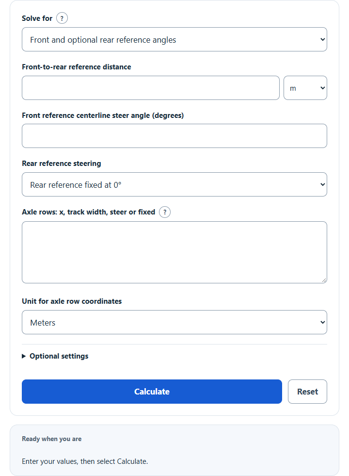
Find ideal wheel steer angles and turning radius for multi-axle and rear-steer vehicles from front and rear angles or a chosen turning center.
Coordinate system and formulas
Place the rear reference at x = 0 and the front reference at x = L. Positive x points forward, positive y points left and positive steering turns left. For front/rear centerline angles δf and δr, yc = L / (tan δf − tan δr) and xc = −yc tan δr.
A wheel at (x,y) needs δ = atan((x − xc) / (yc − y)). For track width t, the left wheel is at y = t/2 and the right wheel at y = −t/2. Enter one axle per line as x, track width, steer or fixed. Every fixed axle must have x = xc to roll without lateral scrub.
The reported radius is √(xc² + yc²) from the rear reference origin. It is not the vehicle-body swept radius. This model requires the turning center outside every wheel track.
Worked example
With a turning center at (0,5) m, a fixed axle at x = 0 and a steering axle at x = 3 m, both with a 2 m track, the steering axle’s left angle is atan(3/4) = 36.8699°. Its right angle is atan(3/6) = 26.5651°. The rear-reference radius is 5 m.
Frequently asked questions
What happens with equal front and rear angles?
The ideal motion is straight crab motion with no finite turning center. A fixed axle cannot follow a nonzero crab angle without scrub.
Can two fixed axles occupy different x positions?
Not in an exact finite no-slip turn. Real vehicles can turn by tire slip or compliance, which this geometry omits.
Does this prove a steering design is safe?
No. Hardware travel, loads, tire behavior, speed and stability require separate engineering analysis.
Further kinematic context: Lim and colleagues: four-wheel steering and path tracking. The wheel-angle calculation above follows rigid-body tangent geometry.