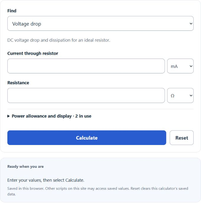
Calculate resistor voltage drop, required series resistor, and divider output voltage from supply, load, current, and resistance values.
Related Calculators
- Series Voltage Calculator
- Internal Resistance Calculator
- Single Phase Power Calculator
- Derating Factor Calculator
- All Physics Calculators
Resistor Voltage Drop Formula
The calculator uses Ohm’s law and standard divider relationships, depending on the mode you choose.
Voltage drop mode — voltage across a resistor when current and resistance are known:
Series dropper mode — resistor needed to drop a supply down to a target voltage at a given load current:
Divider mode — output voltage across the bottom resistor of a two-resistor divider, with optional load:
- V — voltage drop across the resistor, in volts (V)
- I — current through the resistor, in amps (A)
- R — resistance, in ohms (Ω)
- Vs — supply voltage (V)
- Vload — desired voltage at the load (V)
- R1 — top (series) resistor in a divider (Ω)
- R2 — bottom resistor in a divider (Ω)
- Rload — load resistance across R2 (Ω); blank means unloaded
Power dissipated in a resistor is P = I²R = V²/R. The adjustable power allowance factor supplies an arithmetic target; it does not establish a suitable component rating. Verify the chosen part’s temperature derating, mounting, maximum voltage and pulse limits in its datasheet. The formulas assume DC, ideal resistors, and a stiff supply. R2 and Rload combine in parallel as R2*Rload / (R2+Rload).
Reference Tables
Illustrative nominal ratings corresponding to a 2× arithmetic allowance. These examples do not establish suitability; consult the actual component datasheet and operating conditions.
| Calculated dissipation | Illustrative nominal rating (2× arithmetic allowance) | Typical package |
|---|---|---|
| ≤ 60 mW | 1/8 W | 0805 SMD, small axial |
| ≤ 125 mW | 1/4 W | Through-hole axial |
| ≤ 250 mW | 1/2 W | Larger axial |
| ≤ 1 W | 2 W | Metal film, large axial |
| > 1 W | At least 2 × the actual dissipation as an arithmetic target; verify the selected part | Ceramic / aluminum-clad |
Illustrative LED forward-voltage and current ranges. Use the specific LED’s datasheet at the intended current and temperature rather than choosing values from color alone.
| LED color | Typical Vf | Typical drive current |
|---|---|---|
| Red | 1.8 – 2.1 V | 10 – 20 mA |
| Yellow / Orange | 2.0 – 2.2 V | 10 – 20 mA |
| Green | 2.1 – 3.3 V | 10 – 20 mA |
| Blue / White | 3.0 – 3.4 V | 15 – 20 mA |
Worked Example
Drive a red LED from 9 V at 15 mA. Use Vf = 2.0 V.
- Voltage to drop: 9 V − 2.0 V = 7.0 V
- Resistor: 7.0 V / 0.015 A = 467 Ω → use 470 Ω (E12)
- Power with the ideal resistor: 7.0 V × 0.015 A = 0.105 W. A 2× arithmetic allowance is 0.210 W; a nominal 1/4 W part exceeds that target, but its datasheet and operating conditions still require verification.
FAQ
Does the resistor’s tolerance matter? Tolerance affects current and divider output. Choose resistor tolerances from the circuit’s accuracy requirements and account for supply, load and temperature variation.
Why does my divider output sag under load? A load connected across R2 reduces the effective bottom resistance and changes the output. Use the loaded-divider calculation to quantify this effect; a suitable buffer may be needed when the load varies.
Can I use this for AC? Only for purely resistive loads at low frequency. Reactive loads need impedance, not resistance.
Why double the power rating? A factor of 2 is an illustrative allowance, not a universal design rule. Allowable power depends on the actual resistor’s derating curve, cooling, mounting, pulse conditions and voltage limits; verify these against the operating conditions.