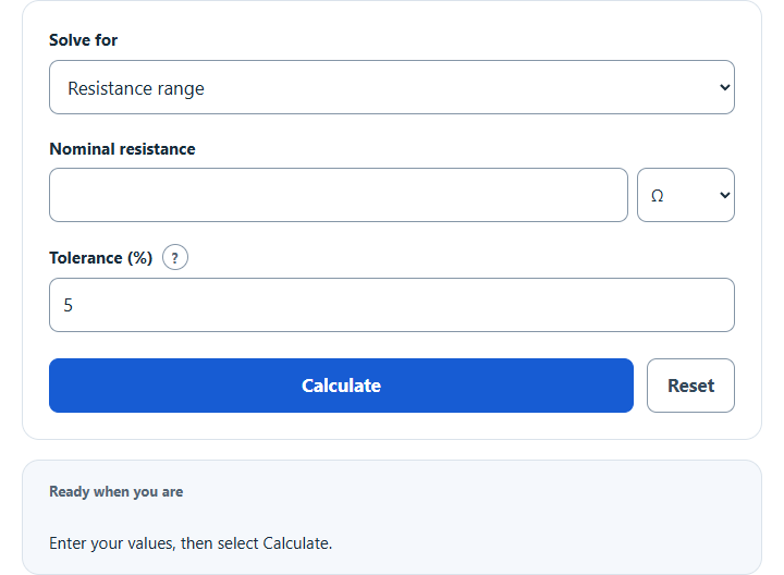
Calculate a resistor’s tolerance range: enter the nominal resistance and tolerance percent (gold band = 5%) to get the minimum and maximum resistance.
Related Calculators
- Resistor Noise Calculator
- Capacitor Charge Time Calculator
- Applied Voltage Calculator
- DC Power Calculator
- All Physics Calculators
Resistor Tolerance Formula
Initial resistor tolerance specifies allowed resistance limits relative to the labeled value under the part’s stated reference and test conditions. It is separate from temperature coefficient, load effects, aging and measurement uncertainty. The calculator above determines the absolute tolerance in ohms from the nominal resistance and the percentage tolerance. This is useful when you need to know the acceptable spread of a resistor in a circuit rather than just the printed percentage.
- T = resistor tolerance in ohms
- R = nominal resistance value
- P = tolerance percentage
Once the tolerance amount is known, the specified limits for a conforming part are a minimum-to-maximum range. These bounds do not specify a probability distribution or confidence level.
What the Result Means
The output of this calculator is the allowable deviation from the stated resistance. If a resistor is labeled 1,000 Ω with a 5% tolerance, that does not mean the resistor is exactly 1,050 Ω or 950 Ω; it means the actual part is allowed to be anywhere inside that band. In practical terms, tolerance tells you how tightly controlled the component value is during manufacturing.
How to Calculate Resistor Tolerance
- Enter the nominal resistance value.
- Enter the resistor tolerance percentage.
- Multiply the nominal resistance by the tolerance percentage.
- Divide by 100 to get the absolute tolerance in the same unit as the resistance.
- Subtract that value from the nominal resistance to find the minimum possible resistance.
- Add that value to the nominal resistance to find the maximum possible resistance.
Example
A 220 Ω resistor with a 5% tolerance has an allowable variation of 11 Ω. That means the actual resistor may measure anywhere from 209 Ω to 231 Ω.
Why Resistor Tolerance Matters
Tolerance affects how closely a real circuit matches its design target. In some applications, a small variation is harmless. In others, it changes voltages, currents, timing, gain, or filter behavior enough to matter.
- Voltage dividers: Wider tolerance can shift the output voltage away from the intended value.
- Current limiting: Tolerance changes current through LEDs and other components.
- Precision analog circuits: Signal conditioning, feedback networks, and instrumentation often require tighter tolerance parts.
- Timing and filtering: RC time constants and cutoff frequencies move as resistor values move.
- Replacement parts: Matching both resistance and tolerance helps preserve circuit performance.
Common Tolerance Values
Lower tolerance percentages specify tighter initial resistance limits. A 1% specification gives a narrower allowed interval than 5% or 10%; it does not by itself guarantee better temperature stability or circuit accuracy. The application descriptions below are informal examples, not certified precision classes.
| Tolerance | Informal description | Typical Use |
|---|---|---|
| ±0.1% | Very high precision | Instrumentation, calibration, precision analog design |
| ±0.25% | High precision | Measurement circuits and tight divider networks |
| ±0.5% | High precision | Control circuits and accurate reference paths |
| ±1% | Precision | General electronics where stable design values matter |
| ±2% | Moderate precision | Standard signal and control circuits |
| ±5% | General purpose | Common through-hole designs, current limiting, pull-ups |
| ±10% | Loose tolerance | Non-critical circuits and basic loads |
| ±20% | Very loose tolerance | Older or highly non-critical applications |
Resistor Tolerance Color Bands
In the referenced common commercial four- and five-band schemes, the tolerance band identifies the specified percentage. The table includes gray at 0.05%; no tolerance band means 20%, not 0%. Extra bands and other marking schemes can represent different specifications, so check the actual part’s datasheet. See the Vishay five-band chart and Vishay commercial color chart.
| Band Color | Tolerance |
|---|---|
| Brown | ±1% |
| Red | ±2% |
| Green | ±0.5% |
| Blue | ±0.25% |
| Violet | ±0.1% |
| Gray | ±0.05% |
| Gold | ±5% |
| Silver | ±10% |
| No band | ±20% |
Selection Tips
- Do not confuse tolerance with power rating. A resistor can be precise and still have a low wattage rating.
- Do not confuse tolerance with temperature stability. A low-tolerance resistor may still drift with temperature if its temperature coefficient is not suitable.
- Check ratio matching separately. Equal individual tolerance percentages do not guarantee matched resistors. Arrays can specify ratio tolerance and TCR tracking separately; see Vishay guidance on divider and feedback arrays.
- Read the output units. Nominal and absolute-allowance inputs have independent Ω, kΩ and MΩ selectors. The main resistance limits are normalized to Ω; equivalent kΩ and MΩ limits are shown separately.
Percentage and Divider Modes
The percentage mode uses a specified absolute ± allowance: p = 100a/R. It does not infer a tolerance specification from one measured resistance. For a voltage divider, the nominal output is Vin × R2/(R1 + R2). The lowest output uses R1 at its upper limit and R2 at its lower limit; the highest uses the opposite limits. These deterministic bounds assume an unloaded divider, fixed ideal input voltage and independently permitted resistor limits. Source impedance, output loading, input-voltage variation, TCR, self-heating and aging are excluded. A matched array’s ratio specification can justify different bounds. Tolerance is not a measurement-confidence interval; see NIST terminology guidance.
Resistor Tolerance FAQ
Is tolerance the same as the total resistance range?
No. Tolerance is the amount the resistor may vary above or below the nominal value. The total span from minimum to maximum is twice the absolute tolerance.
Does a lower tolerance always mean a better resistor?
Not always. Lower tolerance means the resistance value is closer to the target value, but the best choice depends on the circuit. For many simple applications, a wider tolerance resistor performs perfectly well.
Can the actual resistor measure anywhere inside the tolerance band?
A conforming part can lie below, above or near nominal within its specified initial limits under the stated test conditions. Operating temperature and aging can change its value. A single measured deviation does not determine the manufacturer’s tolerance, and measurement uncertainty matters in a conformance decision.
Why is absolute tolerance useful if the resistor already shows a percentage?
The percentage tells you the relative error, but the absolute tolerance tells you the real amount of variation in ohms. That is the value you use when checking minimum and maximum circuit conditions.