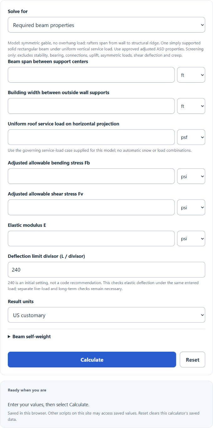
Calculate ridge beam line load, support reactions, shear, bending moment, required section modulus and inertia, or check a rectangular beam for stress and deflection.
Related Calculators
- Load Density Calculator
- Steel Deflection Calculator
- Moment Of Resistance Calculator
- Deck Post Spacing Calculator
- All Construction Calculators
Ridge Beam Formula
These formulas screen a simply supported ridge beam carrying a uniform vertical service load. For a symmetric gable without overhang load, the ridge tributary width is half the building width. Rafters must span from outside walls to the structural ridge. The result is not a selected beam size or structural approval.
- Where Sreq is the required bending section modulus (in³); the factor 12 converts lb·ft to lb·in.
- s is additional beam self-weight (lb/ft), omitted only if already included in the supplied roof load.
- Fb is the approved adjusted allowable bending stress for the material and design case (psi).
- W is horizontal building width between outside wall supports; L is beam span between support centers (ft).
- q is the uniform vertical service load on the horizontal roof projection (psf). Roof slope is not an additional cosine factor for this load basis.
What is a Ridge Beam?
A ridge beam is a structural element used in construction, specifically in roof framing. It runs along the apex of a sloping roof, essentially the highest horizontal line of the roof, and is designed to support the roof's load, distributing the weight of the roof onto the walls of the structure. This model assumes rafters bearing at the ridge and outside walls; it does not model a trussed roof, ridge board, cantilever, continuous beam or concentrated load. Stability, bearing, connections, uplift and the complete load path require separate qualified design.
How to Calculate Ridge Beam?
Use the following steps to screen required section properties or a solid rectangular section. This uses one entered service-load case; it does not select a code load combination, material adjustment factors or a safe beam.
- First, obtain the governing uniform vertical service load q on the horizontal roof projection and confirm that the stated symmetric roof/support model applies.
- Next, determine the beam span L between support centers.
- Next, determine horizontal building width W between the outside wall supports.
- Enter approved adjusted bending and shear allowables Fb and Fv, elastic modulus E, the deflection divisor, and actual section dimensions for a rectangular check. L/240 is an initial setting, not a code recommendation.
- Select Calculate. Bending requires S ≥ M/Fb using consistent force-length units; rectangular shear requires A ≥ 1.5V/Fv. Elastic bending deflection is δ = 5wL⁴/(384EI), so Ireq = 5wL⁴/(384Eδallow), with δallow = L/divisor. Use w in lb/in and L in inches with psi and inch section properties. The same entered load is used for deflection; separate live-load, shear-deformation and long-term checks remain necessary.
Example Problem:
Use the following variables as an example problem to test your knowledge.
Uniform horizontal-projection roof load q = 40 psf; additional beam self-weight s = 0 lb/ft.
Beam support-center span L = 10 ft.
Horizontal building width W = 8 ft.
Adjusted Fb = 5,000 psi, adjusted Fv = 285 psi, E = 1,900,000 psi, and deflection divisor 240. Then w = 160 lb/ft; each reaction = 800 lb; M = 2,000 lb·ft; Sreq = 4.8 in³; rectangular shear area ≥ 4.210526 in²; Ireq = 37.894737 in⁴. These are example arithmetic inputs, not recommended material values or an approved beam.