Calculate steel beam and plate deflection, bending stress, and load limits for various supports, loads, and cross-sections or shapes.
Steel Deflection Formula
For a simply supported steel beam carrying a uniformly distributed load over the full span, the maximum deflection occurs at midspan. This calculator uses the classic elastic beam equation for that case.
This relationship is especially sensitive to span length. Deflection grows with the fourth power of the span, so a longer beam can become much more flexible even if the load only increases slightly. Increasing the section stiffness or using a material with a higher modulus reduces deflection.
What Each Variable Means
| Symbol | Meaning | Common units |
|---|---|---|
| δ | Maximum midspan deflection | in, mm, cm, m |
| w | Uniform load per unit length on the beam | lb/in, lb/ft, kN/m |
| L | Beam span length | in, ft, cm, m |
| E | Modulus of elasticity of the steel | psi, kPa, MPa, GPa |
| I | Second moment of area, also called area moment of inertia | in4, cm4, m4 |
Rearranged Forms
If you know the deflection and need to solve for a different variable, the same beam relation can be rearranged as follows.
How Deflection Changes
The formula makes the beam behavior easy to interpret:
- More load produces more deflection in direct proportion.
- Longer spans increase deflection very rapidly.
- Higher modulus of elasticity and larger moment of inertia make the beam stiffer.
- A deeper beam often reduces deflection significantly because depth strongly affects the moment of inertia.
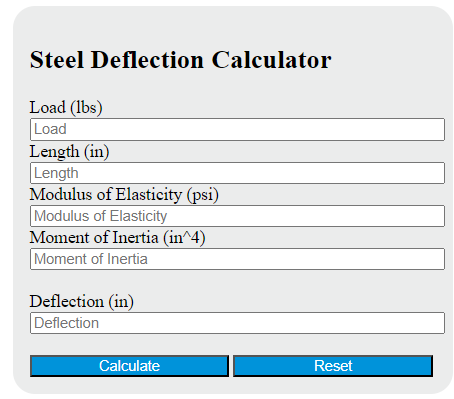
How to Use the Steel Deflection Calculator
- Enter the uniform load acting on the beam.
- Enter the clear span length.
- Enter the modulus of elasticity for the steel being used.
- Enter the section moment of inertia about the axis of bending.
- Calculate the missing value and verify that the resulting deflection is acceptable for serviceability.
For most structural steel applications, the elastic modulus is commonly taken near 29,000 ksi in US customary units or about 200 GPa in SI units. The moment of inertia must match the actual bending axis. If the beam bends about its weak axis, use the weak-axis value of I, not the strong-axis value.
Unit Consistency Matters
When solving by hand, all inputs must be in one consistent unit system. If the modulus is entered in psi and the moment of inertia is in in4, then the span should be in inches and the distributed load should be in force per inch. The calculator handles the unit selections for you, but the physical relationship remains the same.
Example
Assume a simply supported steel beam carries a uniform load of 240 lb/ft over a 10 ft span. Let the modulus of elasticity be 29,000,000 psi and the moment of inertia be 20 in4. After converting to an inch-based system, substitute into the beam equation:
This means the center of the beam moves downward by a little under one tenth of an inch under the stated service load.
When This Formula Applies
- The beam is simply supported at both ends.
- The load is uniformly distributed over the full span.
- The beam remains in the elastic range.
- Deflections are small enough for standard beam theory to apply.
- The section properties and material stiffness are constant along the span.
When You Should Use a Different Deflection Equation
- Point loads or multiple concentrated loads
- Cantilever beams
- Fixed-end or partially restrained supports
- Partial-span distributed loads
- Composite sections or changing section geometry
- Large-deflection or nonlinear behavior
Practical Design Notes
- Deflection is a serviceability check, not only a strength check.
- Excessive deflection can damage finishes, create ponding issues, or cause vibration and alignment problems.
- Always include beam self-weight when it is relevant to the service load.
- If calculated deflection is too large, common fixes include shortening the span, selecting a section with a larger moment of inertia, adding supports, or reducing the distributed load.
- Acceptable deflection limits depend on the use of the member and the project criteria.