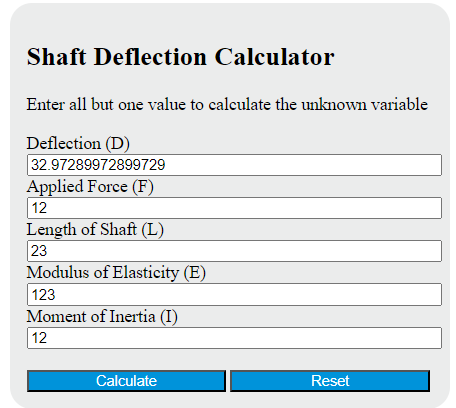
Calculate cantilever shaft deflection, force, length, modulus of elasticity, or inertia from four known inputs with unit selection.
- All Physics Calculators
- Shaft Torque Calculator
- Bending Stress Calculator
- Plate Deflection Calculator
- Cantilever Load Calculator
- Beam Size Calculator
Shaft Deflection Formula (Cantilever, End Point Load)
This calculator uses the classic cantilever-beam deflection equation for a shaft that is fixed at one end, free at the other, and loaded by a single transverse point force at the free end. Under those conditions, the free-end deflection is:
In this relationship, deflection depends most strongly on length because length is raised to the third power. Small increases in unsupported length can create large increases in shaft movement.
| Variable | Meaning | Typical SI Unit |
|---|---|---|
| D | Deflection at the free end | m |
| F | Applied transverse force | N |
| L | Unsupported shaft length | m |
| E | Modulus of elasticity of the shaft material | Pa |
| I | Area moment of inertia about the bending axis | m4 |
Rearranged Forms
Because the calculator can solve for any one missing variable, the same equation can be rearranged as follows:
Applied force from known deflection:
Unsupported length from known deflection:
Required modulus of elasticity:
Required area moment of inertia:
What Shaft Deflection Means
Shaft deflection is the sideways displacement of a shaft under load. In real machines, excessive deflection can lead to bearing misalignment, seal wear, increased vibration, poor gear contact, uneven belt tracking, and reduced service life. Even when a shaft is strong enough to avoid yielding, it may still deflect too much for the system to operate smoothly.
That is why shaft design usually checks both strength and stiffness. This calculator addresses the stiffness side by estimating how far the free end moves under load.
How to Use the Calculator
- Enter any four known values and leave the unknown field blank.
- Use consistent units throughout the calculation.
- Make sure the loading case matches this page: fixed-free shaft with a point load at the free end.
- Confirm that the moment of inertia corresponds to the actual cross-section and bending axis.
- Review the result in a convenient output unit such as mm or in.
If your shaft is supported at both ends, carries multiple loads, has a distributed load, or is stepped along its length, this simplified equation is not the correct model.
Why Length Matters So Much
For this loading case, deflection follows these proportional trends:
- If the force doubles, deflection doubles.
- If the modulus of elasticity doubles, deflection is cut in half.
- If the area moment of inertia doubles, deflection is cut in half.
- If the unsupported length doubles, deflection becomes 8 times larger.
This cubic length effect is one of the most important design insights for shafts, beams, brackets, and cantilevered machine members.
Common Area Moment of Inertia Formulas
The most common source of input error is the area moment of inertia, I. Use the section property about the axis that resists the applied bending.
Solid circular shaft:
Hollow circular shaft:
Rectangular section:
Here, d is diameter for a solid shaft, D is outer diameter for a hollow shaft, d in the hollow-shaft formula is inner diameter, b is width, and h is the dimension measured in the bending direction.
Material Stiffness and the Role of E
The modulus of elasticity, E, measures how resistant a material is to elastic deformation. A higher value of E means the same shaft geometry will deflect less under the same load. Geometry and material both matter, but in many shaft applications, increasing diameter is often more effective than changing material because I changes rapidly with section size.
For round shafts especially, stiffness is very sensitive to diameter because:
That means a modest increase in diameter can produce a large increase in bending stiffness.
Example
Suppose a cantilever shaft has:
- Applied force = 500 N
- Length = 0.5 m
- Modulus of elasticity = 2.1 × 10¹¹ Pa
- Area moment of inertia = 1.5 × 10⁻⁶ m4
Substitute into the formula:
The resulting deflection is:
Which is approximately:
Assumptions Behind This Calculator
- The shaft behaves elastically and returns to shape after load removal.
- Deflection is small relative to shaft length.
- The material is uniform and isotropic.
- The cross-section is constant over the loaded span.
- The load acts perpendicular to the shaft centerline.
- The support at one end is fully fixed.
- Shear deformation is neglected, which is typically acceptable for slender shafts.
Practical Design Notes
- Use the unsupported length, not the total overall shaft length unless they are the same.
- Be careful with unit conversion when switching between Pa, GPa, psi, m, mm, and in.
- For rotating shafts, acceptable deflection is often limited by alignment and vibration requirements, not just by strength.
- If bearings support the shaft at more than one location, use a different beam model.
- If loads are combined from gears, pulleys, or overhung masses, calculate the correct equivalent loading case before using a simplified equation.
When This Calculator Is Most Useful
This calculator is best for quick estimates of cantilevered shafts, overhung members, short projecting spindle sections, fixture arms, and machine elements where a single end load dominates the bending response. It is especially useful early in design when comparing material choices, shaft diameters, or unsupported lengths to see which change most effectively reduces deflection.