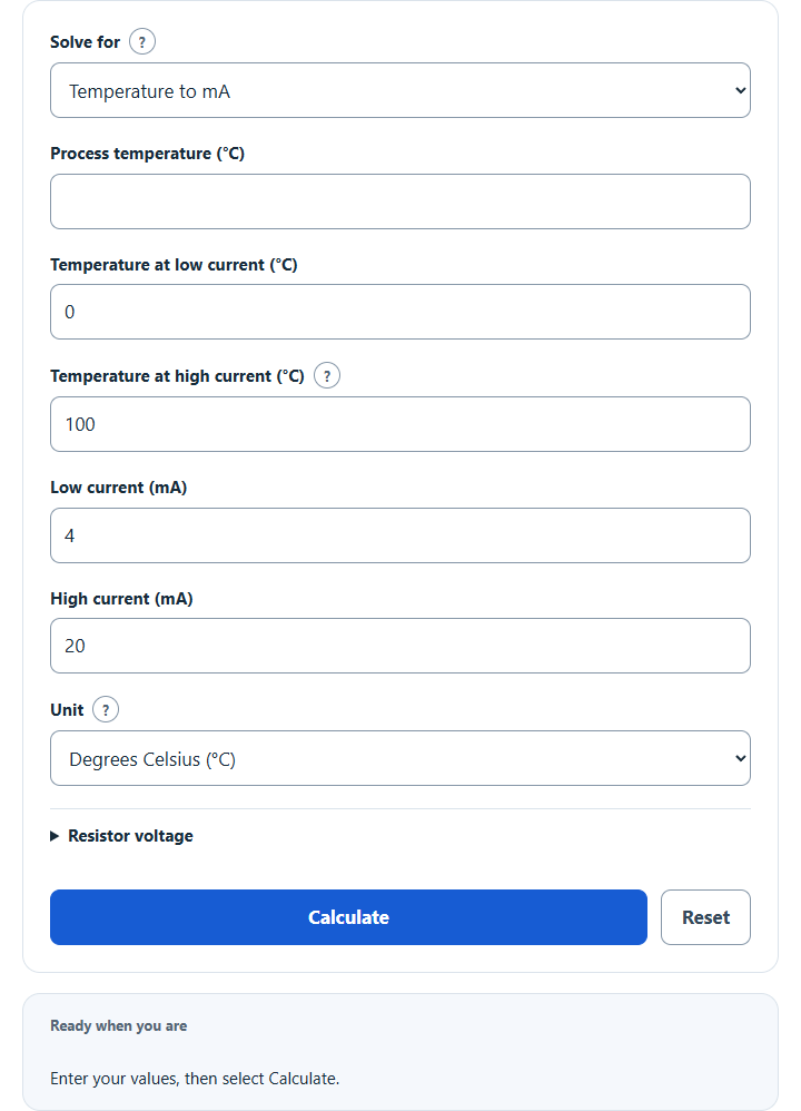
Convert temperature to 4–20 mA or mA to temperature for any transmitter range, with percent of span, calibration points and loop resistor voltage.
- Electricity, Magnetism, & Electronics Unit Converters
- All Unit Converters
- Celsius To Fahrenheit Converter Calculator
- Celsius To Kelvin Converter Calculator
Temperature to 4-20mA Formula
To convert a process temperature into a 4-20mA transmitter output, use:
To convert a measured 4-20mA current back into temperature, use:
The equations above use standard 4 and 20 mA endpoints. For configured pairs (T₀, I₀) and (T₁, I₁), use f = (T − T₀) / (T₁ − T₀) and I = I₀ + f × (I₁ − I₀). The inverse uses f = (I − I₀) / (I₁ − I₀) and T = T₀ + f × (T₁ − T₀). “Below” or “above” refers to fraction of signal span, which need not be numerical temperature order when the temperature span is reversed.
Where:
I is the loop current in milliamps (mA). The standard span runs from 4 mA at the bottom of the range to 20 mA at the top, giving a 16 mA span.
T is the process temperature you are reading or converting.
In these standard-span equations, Tmin is the temperature assigned to 4 mA. More generally, it is the temperature assigned to the configured low current; it need not be the numerically lower temperature in a reverse-acting mapping.
In these standard-span equations, Tmax is the temperature assigned to 20 mA. More generally, it is the temperature assigned to the configured high current. The two temperature endpoints must differ; the high current must exceed the low current.
The standard signal uses a 4 mA live zero. An unexpected 0 mA lies outside the normal 4–20 mA measurement span and may indicate a loop or power problem, but this calculation cannot identify the cause. Device-specific alarm, saturation and loading behavior must be checked separately. A configured 0–20 mA model can legitimately have zero at its low endpoint.
4-20mA Output Reference
The table below gives calculated reference targets for a linear 0-to-100 temperature range mapped to standard 4–20 mA. Use one consistent temperature unit for the range and process input. These values are reference arithmetic, not measured calibration results or proof of instrument accuracy.
| Temperature | Span % | Current (mA) |
|---|---|---|
| 0 | 0% | 4.0 |
| 25 | 25% | 8.0 |
| 50 | 50% | 12.0 |
| 75 | 75% | 16.0 |
| 100 | 100% | 20.0 |
With standard 4–20 mA endpoints, 50% of span is 12 mA regardless of the temperature endpoints. For a custom current span, the midpoint is (low current + high current) / 2; a 0–20 mA span gives 10 mA at 50%. The equivalent standard 4–20 mA output is shown separately from the configured current.
Example Problems
Example 1. A transmitter is ranged from -50 to 150 degrees. You want the output current at a process temperature of 50 degrees. The range is 150 – (-50) = 200 degrees. The fraction of span is (50 – (-50)) / 200 = 0.5. The output is 4 + 0.5 times 16 = 12 mA.
Example 2. The same transmitter reads 16 mA. To find the temperature, the fraction of span is (16 – 4) / 16 = 0.75. The temperature is -50 + 0.75 times 200 = 100 degrees.
FAQ
Why does the standard signal begin at 4 mA instead of 0 mA? The live-zero convention separates the ordinary low-end measurement from zero current. Zero can be a warning sign in a standard loop, but it does not by itself identify a wiring or power fault. Consult the specific instrument and configuration; this tool does not diagnose loop faults.
When does this scaling apply? Use it when the configured output is linear in the stated temperature quantity and the endpoint pairs match that configuration. Real transmitters may apply sensor linearization, saturation, alarm currents and compliance limits that this ideal model does not evaluate.
What if my transmitter uses a different current span? Enter the visible low and high current values, such as 0 and 20 mA. The high value must exceed the low value. Signed custom currents and decreasing temperature endpoints remain supported as algebraic mappings; they do not establish hardware compatibility. Points outside 0–100% are extrapolated without clamping.
The optional resistor field is under Optional resistor voltage. Blank omits the voltage result; an explicit 0 Ω produces an ideal 0 V. For a supplied nonnegative resistance, V = I(mA) × R(Ω) / 1,000. A 250 Ω resistor gives 1, 3 and 5 V at 4, 12 and 20 mA respectively. This calculation does not verify loading, supply compliance, wiring or physical calibration. The C/F selector reinterprets the entered temperature numbers; it does not convert the entire calibration.
References: NI current-loop fundamentals; Texas Instruments on loop loading and compliance; Emerson 3144S configuration, alarm and calibration guidance. Follow the applicable device documentation for hardware procedures.