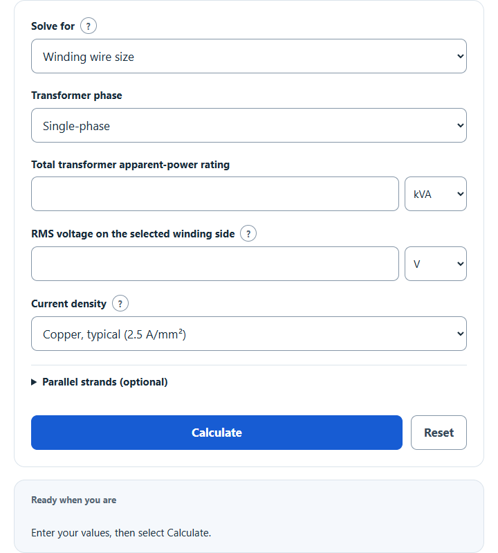
Calculate transformer winding wire size in AWG and mm² from kVA, voltage and phase, using a typical copper current density or your own value.
Transformer Wire Size Formula
This calculator estimates bare winding-conductor area from RMS winding current and a specified current density. It does not determine external feeder size or a complete transformer design.
Minimum total bare area = Iwinding / J
Minimum bare area per equal strand = Iwinding / (J × n)
Single-phase: Iwinding = S / V
Three-phase wye: Iwinding = S / (√3 × VLL)
Three-phase delta: Iwinding = S / (3 × VLL)
Variables:
- Area is bare conductor cross-sectional area in mm²; insulation is excluded.
- S is total apparent-power rating in VA; convert kVA to VA by multiplying by 1,000.
- V is full winding-terminal RMS voltage for single-phase; VLL is line-to-line RMS voltage for balanced three-phase.
- J is the specified RMS current density in A/mm²; it must suit the complete winding design.
- n is the number of equal parallel strands per winding; blank means one strand.
Calculate the winding current on the selected transformer side, divide it by the specified current density, then divide by the number of equal parallel strands. The calculator selects the smallest included bare round AWG area at least as large as the unrounded per-strand requirement, from AWG 40 through 4/0. A requirement above 4/0 is reported without a gauge selection. Power factor and efficiency are not needed when total apparent-power rating is supplied.
What is a Transformer Wire Size?
A transformer wire size refers to the diameter of the wire used in the construction of a transformer. The size of the wire directly affects the transformer’s efficiency and performance. Larger wire sizes can carry more electrical current, reducing power losses and improving efficiency. However, they also increase the size, weight, and cost of the transformer. Therefore, selecting the appropriate wire size is crucial in transformer design to balance performance, cost, and size considerations.
How to Calculate Transformer Wire Size?
The following steps estimate winding wire size under the stated RMS current-density model:
- Select winding wire size, winding current, or transformer rating.
- Select single-phase or balanced three-phase; for three-phase, select the winding connection Y or Δ.
- For wire or current, enter total apparent-power rating and RMS voltage on the same winding side. Three-phase voltage is line-to-line.
- For wire size, keep the typical 2.5 A/mm² copper current density, pick another typical value, or enter the density your design uses.
- Optionally enter 1–50 equal parallel strands. Blank means one; the AWG choice applies to each strand.
- Select Calculate and review the line/winding current, minimum area and bare AWG dimensions. For rating mode, enter winding RMS current and voltage. Verify the complete thermal, insulation and mechanical design separately.
Example Problem:
Use the following variables as an example problem to test your knowledge:
Total apparent-power rating = 10 kVA; single-phase.
Full winding voltage = 240 V RMS.
Specified current density = 3 A/mm²; one strand. This is an example basis, not a universal recommendation.
Winding current = 10,000 / 240 ≈ 41.666667 A. Minimum bare area ≈ 13.888889 mm²; AWG 6 is too small, so the included next-larger choice is AWG 5 (about 16.77 mm²). Insulation increases finished diameter; temperature rise, winding fit, protection and frequency effects need separate checks.