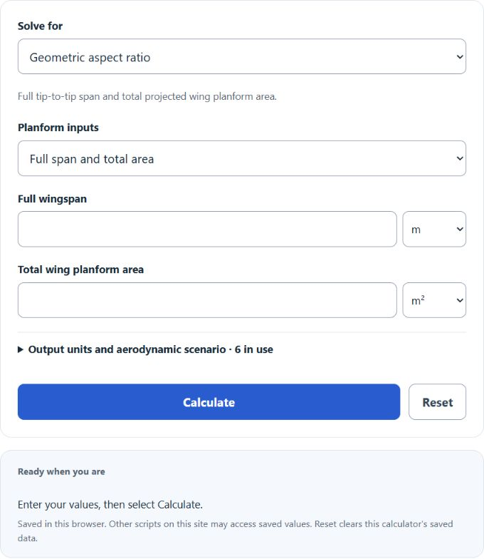
Calculate wing aspect ratio from wingspan and wing area, or solve for span, area and mean chord, with taper ratio, MAC and effective AR.
Calculator Functions
| Function | What it does | What it requires |
|---|---|---|
| Geometric aspect ratio | Finds the aspect ratio of a wing from its span and area, or from its span and chords | Requires the full wingspan and the total wing area, or the span with a constant chord, or the span with root and tip chords |
| Full wingspan | Finds the tip-to-tip span that gives a chosen aspect ratio | Requires the aspect ratio and the total wing area |
| Total wing area | Finds the wing area that gives a chosen aspect ratio | Requires the aspect ratio and the full wingspan |
| Mean geometric chord | Finds the average chord of the wing | Requires the aspect ratio and the full wingspan |
Span and chords go in as meters, feet, inches or centimeters, and area in the squares of those units. Span is the full distance from tip to tip, and area is the projected planform area of both wing halves together. Optional settings estimate an induced-drag coefficient and a lift-curve slope from an Oswald efficiency factor (0.8 if left blank), a lift coefficient (0.4 if left blank) and a 2D lift-curve slope (2π per radian if left blank). An illustrative correction for sweep and winglet height can be switched on for those two estimates.
Wing Aspect Ratio Formulas
| AR | Aspect ratio (no unit) |
| b | Full wingspan, tip to tip |
| S | Total wing planform area, in the square of the unit used for b |
NASA defines aspect ratio as the span squared divided by the wing area, which for a rectangular wing reduces to span divided by chord [1]. A long, narrow wing has a high aspect ratio and a short, wide wing has a low one.
Geometric aspect ratio
The formula above applies directly. A wing with a 30 ft span and 250 ft² of area has AR = 30² ÷ 250 = 3.6. With the rectangular input, area is span × chord, so a 10 m span with a 1.25 m chord has AR = 10 ÷ 1.25 = 8. With the trapezoid input, area is span × (root chord + tip chord) ÷ 2, so a 12 m span with a 2 m root and a 1 m tip has 18 m² of area and AR = 144 ÷ 18 = 8.
÷ (r + t)
The chord inputs also give the length of the mean aerodynamic chord (MAC), where r is the root chord and t is the tip chord of a straight-tapered wing. The 2 m root and 1 m tip above give ⅔ × 7 ÷ 3 = 1.556 m. For a rectangular wing the MAC is the chord itself.
Full wingspan
An aspect ratio of 8 on 18 m² of wing area needs a span of √(8 × 18) = 12 m.
Total wing area
A 12 m span at an aspect ratio of 8 has 12² ÷ 8 = 18 m² of wing area.
Mean geometric chord
A 12 m span at an aspect ratio of 8 has a mean geometric chord of 12 ÷ 8 = 1.5 m. This is the plain average chord. It equals the mean aerodynamic chord only for a rectangular wing, and span and aspect ratio alone cannot give the MAC of a tapered wing.
Induced drag and lift-curve slope
CL is the lift coefficient and e is the efficiency factor, which is 1 for an elliptical lift distribution and lower for every other shape. NASA gives 0.7 for a rectangular wing [1]. At AR = 3.6, e = 0.8 and CL = 0.4, the induced-drag coefficient is 0.16 ÷ (π × 0.8 × 3.6) = 0.0177. Doubling the aspect ratio halves it.
(π × e × AR))
Here a is the lift-curve slope of the finished wing and a₀ is the slope of its airfoil section, both per radian. NASA writes the same reduction for the lift coefficient, without the efficiency factor [2]. With a₀ = 2π, e = 0.8 and AR = 3.6, the slope falls from 6.283 to 3.708 per radian, or 0.0647 per degree.
When the illustrative correction is chosen, both estimates use AR × cos²(sweep) × (1 + 1.9 × winglet height ÷ span) in place of AR. A 12 m span at AR 8 with 25° of sweep and 0.6 m winglets gives 8 × 0.8214 × 1.095 = 7.195. This is a rule of thumb. The geometric aspect ratio and the wing area do not change.
Limits of This Estimate
- Aspect ratio is geometry only. It does not by itself predict lift, drag or whether a design will fly well.
- Area is the projected planform of both wing halves, not the upper and lower skin surfaces added together. Winglet area is not added to it.
- The induced-drag and lift-slope figures are simplified estimates that depend on the efficiency factor, lift coefficient and airfoil slope entered. The defaults of 0.8, 0.4 and 2π are examples, not values for a particular aircraft.
- The sweep and winglet correction and the labels from "Very low" to "Extreme" are rough guides, not aircraft classifications. These estimates are based on the best available data and estimations.
Sources
- NASA Glenn Research Center, Induced Drag Coefficient: aspect ratio as span squared over wing area, the induced-drag coefficient and the efficiency factor
- NASA Glenn Research Center, Downwash Effects on Lift: reduction of lift on a wing of finite aspect ratio