Calculate voltage drop, maximum wire distance, or AWG size for copper or aluminum circuits using current, length, voltage, and drop limit.
Related Calculators
- Motor Current Calculator
- 3 Phase Generator Sizing Calculator
- Diode Selection Calculator
- Norton’S Theorem Calculator
- All Physics Calculators
Amp Loss Over Distance Formula
The calculator does not reduce amps along the wire. In a closed circuit the current is the same at every point. What changes over distance is voltage. The wire has resistance, so some of the source voltage is dropped across the conductors before it reaches the load. That is what people usually mean by "amp loss over distance."
The base voltage drop formula is:
- Vdrop = voltage dropped across the wire, in volts
- K = circuit factor: 2 for DC or single-phase 2-wire, 1.732 for three-phase
- I = load current in amps
- R = conductor resistance in ohms per 1000 feet (copper base, multiplied by 1.64 for aluminum)
- L = one-way wire length in feet
From that, the calculator rearranges for the other two modes.
Maximum one-way distance for a chosen drop limit:
Wire size selection picks the smallest AWG whose calculated Vdrop stays at or below your limit:
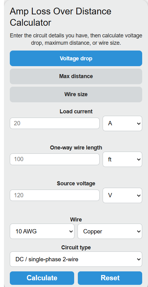
The three tabs map to those three forms. The Voltage Drop tab solves for Vdrop given a wire and length. The Max Distance tab solves for L given a drop limit. The Wire Size tab scans AWG sizes from 40 up to 4/0 and returns the first one that meets the limit.
Reference Tables
Use these values to sanity check the calculator output.
| AWG | Copper Ω/1000 ft | Aluminum Ω/1000 ft | Typical use |
|---|---|---|---|
| 14 | 2.525 | 4.14 | 15 A branch |
| 12 | 1.588 | 2.60 | 20 A branch |
| 10 | 0.999 | 1.64 | 30 A branch |
| 8 | 0.628 | 1.03 | 40-50 A |
| 6 | 0.395 | 0.65 | 55-65 A feeders |
| 4 | 0.249 | 0.41 | 70-85 A feeders |
| 2 | 0.156 | 0.26 | 95-115 A feeders |
| 1/0 | 0.098 | 0.16 | 125-150 A service |
| 4/0 | 0.049 | 0.080 | 200 A service |
Voltage drop targets vary by application. These are common limits used for design work.
| Application | Recommended max drop |
|---|---|
| Branch circuit (NEC informational) | 3% |
| Feeder + branch combined | 5% |
| 12 V DC (RV, solar, marine) | 3% critical, 10% non-critical |
| Motor branch circuits | 3% |
| Low-voltage lighting | 5-10% |
Worked Examples and FAQ
Example 1. A 20 A load on 12 AWG copper at 120 V, single-phase, 100 ft one-way:
Vdrop = 2 × 20 × 1.588 × 100 / 1000 = 6.35 V, or about 5.3%. That is above the 3% target, so you would either step up to 10 AWG or shorten the run.
Example 2. 30 A at 240 V single-phase, 3% drop limit, 10 AWG copper. Max drop = 7.2 V.
Lmax = (7.2 × 1000) / (2 × 30 × 0.999) = 120 ft one-way.
Does current actually drop along the wire? No. Series circuit current is constant. The wire converts a small share of voltage into heat, which is why the calculator reports voltage drop and percent drop instead of an "amp loss" number.
Why use one-way length and not total wire length? The circuit factor of 2 already accounts for the return conductor in DC and single-phase circuits. Entering total loop length would double-count it.
Why is aluminum resistance higher? Aluminum has roughly 61% the conductivity of copper. The calculator multiplies the copper resistance by 1.64 to approximate aluminum at the same AWG.
Does this account for temperature? No. Values are for conductors near 20°C / 68°F. Hot conductors have higher resistance, so real-world drop on a loaded circuit at 75°C will be a few percent higher than the calculated value.