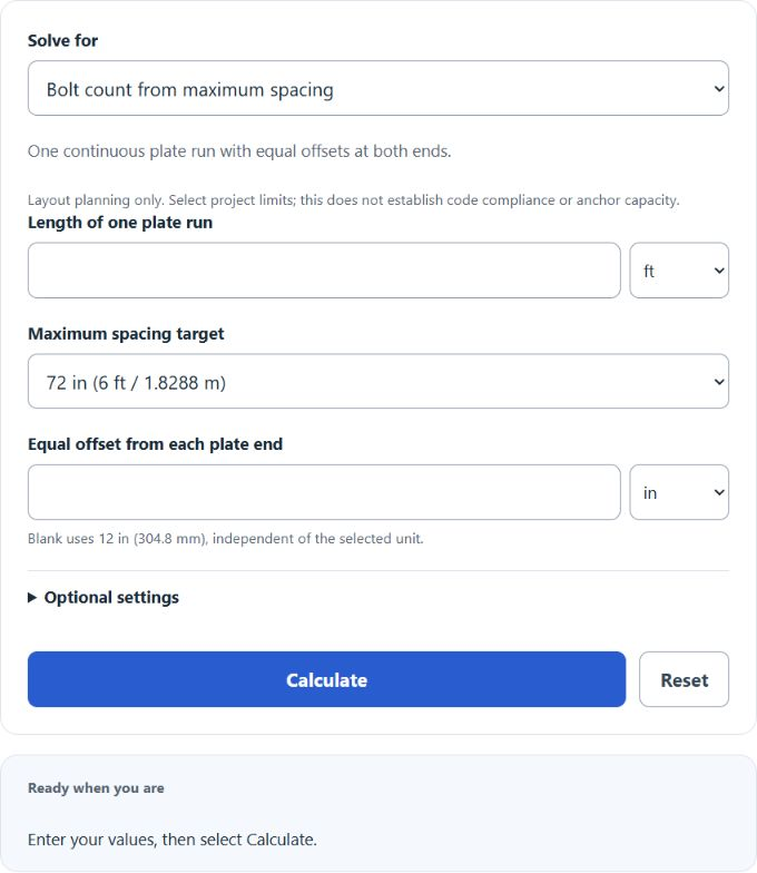
Plan an even anchor-bolt layout from project-selected spacing limits, end offsets and optional uniform-load assumptions. This tool does not establish code compliance or connection capacity.
Anchor Bolt Spacing Formula
The main layout runs in two steps. First it finds how many bolts a run needs, then it spreads them evenly so no gap is too wide. In the equations below N is the bolt count, L is the plate length, e is the end distance, and s is the maximum on-center spacing:
N = max(2, ceil((L - 2e) / s) + 1)
 S = (L - 2e) / (N - 1)
Variables:
- N is the number of anchor bolts in the run, rounded up and never fewer than 2
- L is the length of the sill plate or wall run
- e is the end distance, the gap from each end of the plate to the nearest bolt (default 12 in)
- s is the project-selected maximum on-center spacing; the 6 ft and 4 ft choices are layout targets, not automatic code determinations
- S is the actual on-center spacing after the bolts are spread evenly
The first line takes the length between the two end bolts, divides it by the maximum spacing, and rounds up, so every interior gap stays under the limit. The second line divides that same length by the number of gaps to give one even spacing you can mark out with a tape. Setting the number of bolts yourself flips the second equation around and returns the spacing that count produces, which is useful when you already know how many anchors you have.
The uniform-load planning mode uses a simplified midpoint tributary allocation, not an engineered connection design. C is the user-supplied allowable capacity of one anchor and w is a uniformly distributed design demand per unit length, using consistent design bases:
s = C / w
For three or more anchors, the assumed interior tributary length is S and the end tributary length is e + S/2. The model therefore also limits S to 2(C/w − e), then applies the selected project maximum. With two anchors, each is assigned half the total uniform load and checked separately. L must exceed 2e and C/w must exceed e. These assumptions do not establish actual anchor reactions or account for group effects, uplift, eccentricity or connection failure modes.
Anchor Bolt Requirements at a Glance
The following summarizes selected 2021 IRC provisions, not the locally adopted requirements for every anchor installation. R403.1.6 supplies a 6 ft baseline for the wood sill/sole plates within its scope. R403.1.6.1 applies to wood light-frame structures in D0–D2 and wood light-frame townhouses in C; its 4 ft provision is for buildings over two stories within that scope. High wind does not create a universal 4 ft rule through these sections. Confirm the adopted edition, amendments and project design.
| Requirement | IRC limit |
|---|---|
| R403.1.6 baseline spacing (within its scope) | 72 in (6 ft) on center |
| Maximum spacing, exception | 48 in (4 ft) for buildings over two stories within R403.1.6.1 scope |
| Minimum bolt diameter | 1/2 in (12.7 mm) |
| Minimum embedment | 7 in (178 mm) into concrete or grouted masonry |
| Minimum bolts per plate section | 2 |
| End distance to first and last bolt | Within 12 in (305 mm) of each end, and at least 7 bolt diameters |
| Bolt position across the plate | Middle third of the plate width |
| Plate washers where required by applicable provisions | Confirm required dimensions and detailing for the project |
This second table gives a quick bolt count by wall length at both maximum spacings, assuming a bolt 12 inches from each end. The table assumes a single continuous plate, L greater than 2e, and no joints or additional project constraints. End offsets reduce the span between the first and last anchors.
| Wall length | Bolts at 6 ft max | Bolts at 4 ft max |
|---|---|---|
| 8 ft | 2 | 3 |
| 10 ft | 3 | 3 |
| 12 ft | 3 | 4 |
| 16 ft | 4 | 5 |
| 20 ft | 4 | 6 |
| 24 ft | 5 | 7 |
| 30 ft | 6 | 8 |
| 40 ft | 8 | 11 |
| 50 ft | 9 | 13 |
Example Problems
Example 1: bolts for a 40-foot wall.
For a 40 ft sill-plate planning example, select a project maximum of 6 ft (72 in) and an offset of 12 in from each end. The distance between the two end bolts is 40 ft minus 2 times 12 in, which is 456 in. Divide by 72 in and round up: 456 / 72 = 6.33, which rounds to 7 gaps, so N = 7 + 1 = 8 bolts. Spreading 8 bolts across 456 in gives an actual spacing of 456 / 7 = 65.1 in, about 5.4 ft, which is under the 6 ft limit.
Example 2: load-based spacing.
In the simplified uniform-load model, a 30 ft wall has a design demand of 300 lbf per foot and a project-supplied allowable capacity of 1,500 lbf per anchor. The load-limited spacing is 1,500 / 300 = 5 ft (60 in), which is tighter than the 6 ft maximum, so 60 in governs. Laying the 30 ft run out with a 12 in end distance and a 60 in step gives 7 bolts at an even 56 in on center.
Frequently Asked Questions
What is the maximum spacing for anchor bolts?
The 2021 IRC R403.1.6 baseline is 6 ft within that section’s scope. Its seismic provisions do not impose 4 ft on every Category C or D building: the 4 ft clause concerns buildings over two stories within R403.1.6.1 scope. High-wind design and local amendments can require other provisions. Confirm the project-specific maximum with the applicable authority or design professional.
How many anchor bolts do I need per board?
The usual 2021 IRC R403.1.6 provision is at least two bolts per plate section. Specific short-wall exceptions concern walls connecting offset braced-wall panels with the specified corner attachments; they are not blanket exemptions for any short plate. This calculator models at least two distinct anchors and does not apply those exceptions.
How far from the end of the plate should the first bolt go?
Set the first and last bolt within 12 inches of each end, but not closer than seven bolt diameters. For a 1/2 inch bolt that minimum works out to 3.5 inches. This limited end-distance comparison does not verify concrete edge distance, embedment, uplift or connection strength.