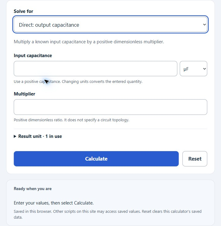
Choose a direct capacitance solve, a simplified BJT filter estimate, or a series/parallel total. Units range from pF to F. The BJT filter is unregulated and its assumptions are shown with the result.
- All Physics Calculators
- Parallel Wire Capacitance Calculator
- Coax Cable Calculator (Impedance-Inductance-Capacitance)
- Capacitance Calculator
Capacitance Multiplier Formula
The following formula is used to calculate the output capacitance:
Variables:
- C_out is the output capacitance (μF)
- C_in is the input capacitance (μF)
- M is the multiplier
To calculate the output capacitance, multiply the input capacitance by the multiplier.
What is a Capacitance Multiplier?
A capacitance multiplier is an electronic circuit that uses an active device (like a transistor) to make a small capacitor function like a capacitor that is much larger. This is useful in power supply filters where large capacitance values are needed to reduce ripple voltage but physical size or cost of large capacitors is prohibitive.
How to Calculate Output Capacitance?
Choose Direct: output capacitance, enter the input capacitance and multiplier, then select Calculate. The following steps describe that solve.
- First, determine the input capacitance (C_in) in microfarads (μF).
- Next, determine the multiplier (M).
- Use the formula from above = C_out = C_in * M.
- Finally, calculate the output capacitance (C_out) in microfarads (μF).
- After inserting the variables and calculating the result, check your answer with the calculator above.
Example Problem:
Use the following variables as an example problem to test your knowledge.
Input capacitance (C_in) = 100 μF
Multiplier (M) = 10; output capacitance = 100 × 10 = 1,000 μF.
The BJT estimate assumes a single base resistor and capacitor feeding an NPN emitter follower with constant load current. It includes base-current resistor drop and an assumed base-emitter drop. A desired output is a comparison, not a regulated setpoint. Ripple uses an ideal RC sinusoidal estimate and is unavailable when forward-active operation is not supported. Dissipation is estimated at the supplied low DC input, not a maximum thermal rating. See Analog Devices’ circuit explanation.