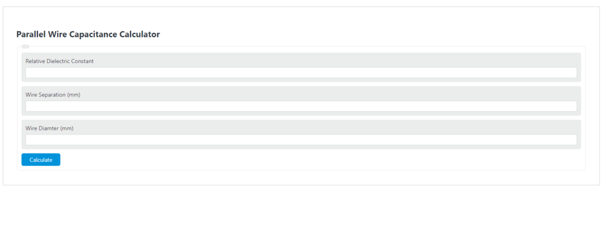
Calculate parallel wire capacitance per unit length, or solve for dielectric constant, wire spacing, or wire diameter from three values.
Related Calculators
- Decoupling Capacitor Calculator
- Capacitance Calculator
- Breakdown Voltage Calculator
- 5/8 Wave Antenna Length Calculator
- Time Domain To Phasor Calculator
- All Physics Calculators
Parallel Wire Capacitance Formula
The calculator uses the capacitance per unit length equation for two parallel round wires in a uniform dielectric. The wire spacing is the center-to-center distance between the two conductors.
Rearranged forms used when a different value is missing:
- C′ = capacitance per unit length, in F/m internally, with output options of pF/m or nF/m
- ε0 = vacuum permittivity, 8.8541878128 × 10⁻¹² F/m
- εr = relative dielectric constant of the material between and around the wires
- s = wire center-to-center spacing
- d = wire diameter
- acosh = inverse hyperbolic cosine
- cosh = hyperbolic cosine
Enter any three values and leave one field blank. The calculator converts length inputs to meters and capacitance inputs to F/m before applying the formula. For the geometry to be valid, s must be greater than d, because the spacing between wire centers must be larger than the wire diameter.
Common Dielectric Constants and Capacitance Units
Use the dielectric constant table as a starting point when the insulation or surrounding material is known. Actual values vary with frequency, temperature, and material grade.
| Material | Typical εr | Notes |
|---|---|---|
| Air | 1.0006 | Often approximated as 1 |
| Polyethylene | 2.25 to 2.35 | Common wire insulation |
| PTFE | 2.0 to 2.1 | Low-loss dielectric |
| PVC | 3.0 to 4.0 | Varies by formulation |
| Rubber | 2.5 to 3.5 | Approximate range |
| Unit | Equivalent in F/m | Equivalent relationship |
|---|---|---|
| 1 pF/m | 1 × 10-12 F/m | 1000 pF/m = 1 nF/m |
| 1 nF/m | 1 × 10⁻⁹ F/m | 1 nF/m = 1000 pF/m |
Example Calculations
Example 1: Find capacitance per unit length
You have two parallel wires in air with a center-to-center spacing of 10 mm and a wire diameter of 1 mm. Use εr = 1.
- s = 10 mm = 0.010 m
- d = 1 mm = 0.001 m
- s/d = 10
- acosh(10) ≈ 2.993223
C′ ≈ 9.29 pF/m
Example 2: Find relative dielectric constant
You measure a capacitance per unit length of 25 pF/m for wires spaced 5 mm apart with a diameter of 1 mm.
- C′ = 25 pF/m = 25 × 10-12 F/m
- s = 5 mm = 0.005 m
- d = 1 mm = 0.001 m
- s/d = 5
- acosh(5) ≈ 2.292432
εr ≈ 2.06
FAQ
What does capacitance per unit length mean?
Capacitance per unit length is the capacitance for each meter of parallel wire run. If the result is 20 pF/m and the wire pair is 3 meters long, the approximate total capacitance is 60 pF, assuming the geometry and dielectric stay the same along the full length.
Why must the wire spacing be greater than the wire diameter?
The spacing value is measured from the center of one wire to the center of the other. If the center-to-center spacing is equal to or smaller than the diameter, the wires would touch or overlap geometrically. The formula also requires acosh(s/d), which is only valid here when s/d is greater than 1.
Does this formula include insulation thickness or nearby objects?
The formula assumes two round parallel conductors in a uniform dielectric. If the wires have insulation, nearby shields, a ground plane, cable jackets, or mixed materials around them, the real capacitance may differ. Use an effective relative dielectric constant only as an approximation when the field passes through more than one material.