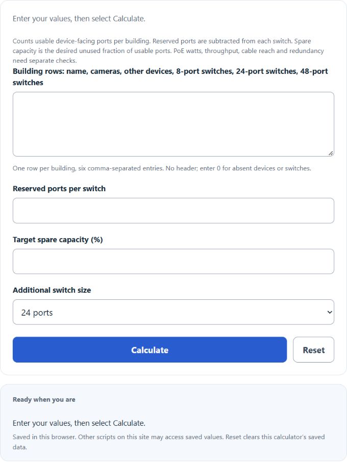
Estimate current port capacity and additional switches for a CCTV network across multiple buildings. Each building keeps its own device demand, usable ports and spare-capacity target.
Capacity formula
Devices = cameras + other devices. Usable ports = Σ[switch count × (nominal ports − reserved ports)]. Required usable ports = ceiling[devices / (1 − spare fraction)]. Additional switches = ceiling[max(0, required − usable)/(new switch size − reserved ports)].
Example
A building has 20 cameras, 2 other devices and one 24-port switch. Reserving two ports leaves 22 usable ports. A 20% spare target needs ceiling(22/0.8) = 28 ports, so the target deficit is six. One additional 24-port switch, with 22 usable ports, covers it.
Frequently asked questions
Should dedicated uplink ports be subtracted?
Only subtract ports that are included in the device-port count and unavailable to endpoints. A separately counted uplink should not reduce the downlink count twice.
Can spare ports in another building cover a shortage?
This calculation assumes local allocations. Additional switch counts are rounded up separately for every building.
Does enough port capacity guarantee the network will work?
It establishes only endpoint-port availability. Check each switch’s PoE budget, uplink bandwidth, redundancy and cabling requirements separately.
Reference: Cisco switch overview distinguishing downlink ports and product configurations.