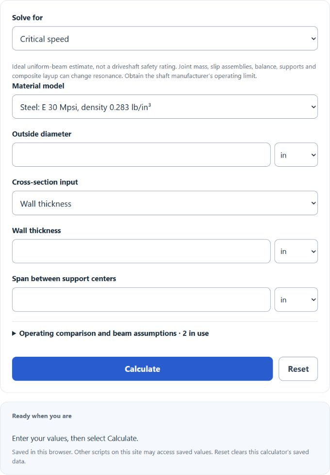
Estimate an ideal uniform shaft’s first critical speed from its dimensions and material, or solve for span or diameter at a chosen operating fraction. This beam estimate is not a certified driveshaft operating limit.
- All Automotive Calculators
- Driveshaft U-Joint Operating Angle Calculator
- Speedometer Driven Gear Calculator
Driveshaft Critical Speed Formula
Critical speed is the rotational speed at which a spinning shaft matches its own first bending resonance. At that speed any small imbalance drives the shaft to bow out, or whirl, with rapidly growing deflection. The whirling speed of a uniform tube follows from beam vibration theory:
Nc = (60 / (2 x pi)) x (lambda^2 / L^2) x sqrt(E x I / (rho x A))
For a round tube the section terms reduce to the outside and inside diameters, which gives the form the calculator uses for any material:
Nc = (60 x lambda^2 / (8 x pi x L^2)) x sqrt(E / rho) x sqrt(OD^2 + ID^2)
For a steel tube with the ends simply supported, the selected approximate material values (E = 30 Mpsi, weight density = 0.283 lb/in³, g = 386.4 in/s²) give the following beam-model coefficient, with OD, ID, and L in inches and Nc in RPM:
Nc ≈ 4,768,668 x sqrt(OD^2 + ID^2) / L^2
A chosen screening fraction defines a comparison level; actual driveshaft application limits also require manufacturer-specific construction corrections and series limits:
N_chosen = f x Nc
- Nc = critical (whirl) speed, in RPM
- OD = tube outside diameter
- ID = tube inside diameter (outside diameter minus twice the wall thickness)
- L = shaft length between the joint or bearing centers
- E = modulus of elasticity of the tube material
- rho = density of the tube material
- I = second moment of area of the tube section
- A = cross-sectional area of the tube wall
- lambda^2 = end-support constant (9.87 for a simply supported shaft, 22.4 fixed at both ends, 3.52 for an overhung shaft)
- f = user-chosen operating fraction; the illustrative default is 0.75 and is not a certified safety rating
The default mode estimates first critical speed, the chosen comparison level and tube-only weight. Operating RPM is optional in this mode. Length and diameter modes require operating RPM and invert the same ideal beam equation. A fixed wall thickness requires outside diameter at least twice that wall; when that solid-section boundary already meets the chosen level, the diameter mode reports that boundary and recomputes the achieved critical speed. A strictly hollow tube must be larger than this boundary. Material presets are approximate; custom properties must describe a homogeneous effective bending model. Composite layups require a separately validated model.
Critical Speed by Tube Length and Material
The first table shows how critical speed and the chosen operating level fall as a common 3.0 inch outside diameter, 0.083 inch wall steel tube gets longer. Because critical speed drops with the square of length, the same tube has a lower modeled resonance at 72 inches than at 48 inches. Values are approximate and assume a simply supported steel tube.
| Shaft length | Critical speed (RPM) | Chosen 75% level (RPM) |
|---|---|---|
| 40 in | 12,300 | 9,230 |
| 48 in | 8,540 | 6,410 |
| 54 in | 6,750 | 5,060 |
| 60 in | 5,470 | 4,100 |
| 66 in | 4,520 | 3,390 |
| 72 in | 3,800 | 2,850 |
The second table explains a result that surprises most people: swapping steel for the same size aluminum tube barely changes critical speed. Critical speed scales with the square root of stiffness over density, and steel, aluminum, and titanium sit within about two percent of each other on that measure. A larger diameter can increase the modeled frequency at fixed wall thickness. Material and assembly choices must also satisfy strength, balance, joint and manufacturer requirements; a generic carbon-fiber modulus is not sufficient to rate a composite shaft. The factor column is the relative critical speed of the same tube size against steel.
| Material | Modulus E | Density | Critical speed factor | Weight vs steel |
|---|---|---|---|---|
| Steel (mild or 4130) | 30 Mpsi (207 GPa) | 0.283 lb/in3 | 1.00 | 1.00 |
| Aluminum 6061 | 10 Mpsi (69 GPa) | 0.098 lb/in3 | 0.98 | 0.35 |
| Titanium 6Al-4V | 16.5 Mpsi (114 GPa) | 0.163 lb/in3 | 0.98 | 0.58 |
| Illustrative composite property pair (not a shaft rating) | about 18 Mpsi (124 GPa) | about 0.055 lb/in3 | about 1.76 | 0.19 |
Example Problems
Example 1: critical speed of a steel shaft. For a 3.0 inch outside diameter, 0.065 inch wall and 48 inch ideal simply supported span, ID = 2.87 inches. Using the stated material model, Nc ≈ 4,768,668.188 × √(3² + 2.87²) / 48² ≈ 8,592.99 RPM. The chosen 75% comparison level is approximately 6,444.74 RPM. These values do not certify the assembled shaft.
Example 2: length at a chosen fraction. For a 3.5 inch outside diameter and 0.083 inch wall, ID = 3.334 inches. With 6,500 operating RPM and a chosen 75% fraction, the modeled required critical speed is 6,500/0.75 ≈ 8,666.67 RPM. The ideal span is L = √[4,768,668.188 × √(3.5² + 3.334²) / (6,500/0.75)] ≈ 51.57230 inches. Actual application limits require the shaft manufacturer’s construction corrections and operating guidance.
Frequently Asked Questions
How close to critical speed can I safely run a driveshaft? This tool cannot determine a safe assembled-shaft speed. Its 75% default is a screening fraction applied to an ideal uniform beam. Dana’s application method also applies construction corrections and series RPM limits; joint mass, slip arrangements, support flexibility, imbalance and half-critical excitation can matter. Use the shaft manufacturer’s application-specific limit.
Does a longer driveshaft raise or lower critical speed? It lowers it. Critical speed falls with the square of length, so making a shaft twice as long cuts its critical speed to about one quarter. That is why long trucks, vans, and lifted vehicles either move up to a larger diameter tube or use a two-piece shaft with a center support bearing. In the ideal model, halving an otherwise identical span quadruples its first bending frequency. An actual two-piece assembly requires separate support and driveline analysis.
Why do steel and aluminum driveshafts of the same size have almost the same critical speed? Critical speed depends on the square root of stiffness divided by density, a property called specific stiffness, and steel, aluminum, and titanium all land within about two percent of each other. Swapping a steel tube for the same size aluminum tube barely moves the critical speed, but it cuts weight by roughly two thirds. This relationship does not rate an assembled or composite shaft; material substitutions require application-specific engineering.