Calculate a high pass filter's resistance, capacitance, or cut-off frequency from any two values, with ohm, farad, and Hz unit conversions.
- All Physics Calculators
- Phase Difference Calculator
- Phase Angle Calculator
- Bandpass Filter Calculator
- Resistance Per Meter Calculator
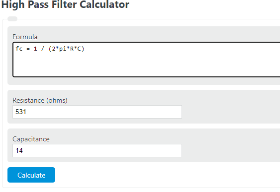
High Pass Filter Formula
For an ideal first-order RC high-pass filter, the cutoff frequency is determined by the resistor and capacitor values:
Where:
- fc = cutoff frequency in hertz (Hz)
- R = resistance in ohms (Ω)
- C = capacitance in farads (F)
If you know the desired cutoff frequency, you can rearrange the equation to solve for the missing component value:
The RC time constant is also closely related to the filter response:
What the Cutoff Frequency Means
The cutoff frequency is the transition point between the attenuated low-frequency region and the higher-frequency pass region. In a first-order high-pass filter:
- Frequencies well below the cutoff are strongly reduced.
- Frequencies near the cutoff are partially attenuated.
- Frequencies well above the cutoff pass with much less attenuation.
At the cutoff frequency, the output amplitude is approximately 70.7% of the passband level, which corresponds to the familiar -3 dB point:
For a simple RC high-pass filter, the ideal transfer function is:
How to Use the Calculator
- Enter any two known values: resistance, capacitance, or cutoff frequency.
- Select the correct units for each input, such as Ω, kΩ, MΩ, F, mF, µF, nF, or pF.
- Click calculate to solve for the missing value.
- Use the result to size components for an RC high-pass filter or to verify an existing design.
This calculator is most useful when designing coupling networks, DC-blocking stages, signal conditioning circuits, and basic audio or sensor filtering applications.
Design Notes for RC High-Pass Filters
| Design change | Effect on cutoff frequency | Practical result |
|---|---|---|
| Increase resistance | Lowers the cutoff | More low-frequency content is allowed through |
| Increase capacitance | Lowers the cutoff | Improves low-frequency coupling |
| Decrease resistance | Raises the cutoff | More low-frequency attenuation |
| Decrease capacitance | Raises the cutoff | Greater blocking of slow or DC-like signals |
Useful rules of thumb:
- Doubling R cuts the cutoff frequency in half.
- Doubling C also cuts the cutoff frequency in half.
- A first-order high-pass filter rolls off at approximately 20 dB per decade below the cutoff.
- To preserve a signal band, the cutoff is typically chosen below the lowest frequency that should pass with minimal loss.
Example Calculations
Finding cutoff frequency from resistance and capacitance
With a resistance of 1 kΩ and a capacitance of 100 nF:
The filter begins transitioning at about 1.59 kHz.
Finding resistance for a target cutoff
For a target cutoff of 200 Hz with a capacitance of 0.1 µF:
A practical resistor choice would be approximately 7.96 kΩ or the nearest standard value.
Unit Tips
- kΩ and MΩ are common for resistor inputs in filter design.
- µF, nF, and pF are common capacitor units.
- Large resistance or capacitance values produce a lower cutoff frequency.
- Small resistance or capacitance values produce a higher cutoff frequency.
- Make sure your entered values reflect the actual installed component sizes, not just nominal labels.
Real-World Considerations
This calculator uses the ideal first-order RC high-pass relationship. In real circuits, the actual response can shift because of:
- component tolerance in resistors and capacitors,
- source impedance from the signal feeding the filter,
- load impedance connected to the filter output,
- parasitic capacitance and wiring effects at higher frequencies,
- multiple cascaded stages that create a steeper overall response.
If the resistor is part of a larger network, the effective resistance seen by the capacitor may differ from the labeled component value, which changes the true cutoff frequency.
FAQ
What does a high-pass filter do?
A high-pass filter attenuates lower-frequency signals and allows higher-frequency signals to pass.
Does an RC high-pass filter block DC?
Yes. In steady-state operation, a capacitor-based RC high-pass filter strongly rejects DC and very slow-changing signals.
What happens if I increase both resistance and capacitance?
The cutoff frequency decreases, because the product of resistance and capacitance becomes larger.
Can this formula be used for active high-pass filters?
It is accurate for a simple ideal first-order RC section. Active filters may use the same cutoff concept, but their full behavior depends on the amplifier configuration and the number of poles.
Why is my measured cutoff slightly different from the calculated value?
Measured results often differ because of component tolerances, loading effects, instrument impedance, and non-ideal behavior in the surrounding circuit.