Calculate inductor reactance, frequency, or inductance from any two values using X_L = 2πfL with selectable Hz, H, and Ω units for ideal inductors.
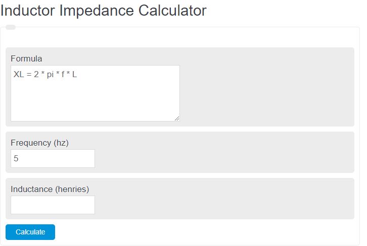
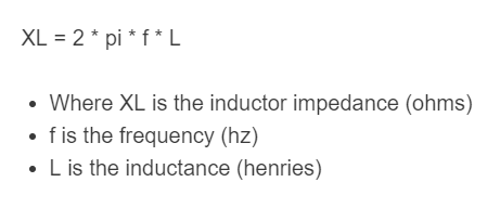
Inductor Impedance Formula
An inductor opposes alternating current by developing inductive reactance. For an ideal inductor, the impedance is purely reactive, so the magnitude of the impedance is the same as the reactance.
- ZL = inductor impedance
- XL = inductive reactance, in ohms
- f = frequency, in hertz
- L = inductance, in henries
- ω = angular frequency
- j = imaginary unit
This means the calculator is finding how strongly an inductor resists AC at a given frequency. If frequency increases, impedance increases. If inductance increases, impedance also increases.
Rearranged Forms
If you know any two values, you can solve for the third.
How to Use the Calculator
- Enter the frequency of the AC signal.
- Enter the inductance of the coil or component.
- Choose the correct units such as Hz, kHz, MHz, H, mH, or µH.
- Read the resulting reactance / impedance magnitude in ohms, kΩ, or MΩ.
If you are solving for frequency or inductance instead, enter the known values and let the calculator determine the missing variable.
How Inductor Impedance Behaves
- Higher frequency produces higher impedance.
- Higher inductance produces higher impedance.
- At steady-state DC, an ideal inductor has zero reactance.
- For an ideal inductor, current lags voltage by 90°.
The relationship is linear. Doubling the frequency doubles the reactance. Doubling the inductance also doubles the reactance.
Example Calculations
For a 10 mH inductor at 1,000 Hz:
For a 250 mH inductor at 60 Hz:
Reference Values
| Frequency | Inductance | Reactance |
|---|---|---|
| 60 Hz | 100 mH | 37.70 Ω |
| 1 kHz | 10 mH | 62.83 Ω |
| 10 kHz | 1 mH | 62.83 Ω |
| 100 kHz | 100 µH | 62.83 Ω |
Unit Conversions
- 1 H = 1000 mH
- 1 mH = 1000 µH
- 1 kHz = 1000 Hz
- 1 MHz = 1,000,000 Hz
- 1 kΩ = 1000 Ω
Always convert values to base units before doing hand calculations if your calculator does not handle unit scaling automatically.
Ideal Inductor vs Real Inductor
This calculator assumes an ideal inductor. Real inductors usually have winding resistance and other parasitic effects, especially at higher frequencies. In a simple series resistance model, the total impedance is:
If resistance is small compared with the reactance, the ideal inductor formula gives a very close estimate.
Common Uses
- Filter design
- AC circuit analysis
- Tuned and resonant circuits
- Power electronics
- Audio crossovers
- RF and signal conditioning circuits
FAQ
Is inductor impedance the same as reactance?
For an ideal inductor, the magnitude of impedance equals the inductive reactance. The full impedance is a complex quantity with phase information.
Why does the calculator increase with frequency?
An inductor resists changes in current. Faster current changes occur at higher frequencies, so the opposition becomes larger.
What happens at 0 Hz?
At steady-state DC, an ideal inductor has zero reactance, so its ideal impedance magnitude is zero.
Can I use mH and kHz directly?
Yes, as long as the calculator supports the selected units. For manual calculations, convert them to henries and hertz first.