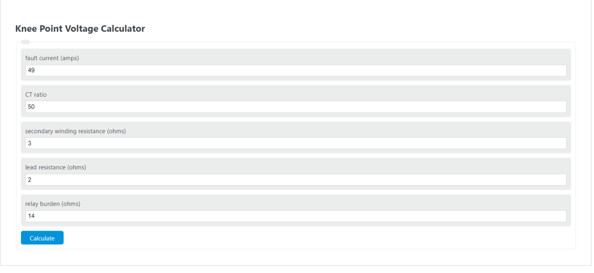
Estimate the required knee-point voltage for a CT from fault current, CT ratio, winding resistance, lead resistance, and relay burden.
- All Physics Calculators
- All Electrical Calculators
- CT Ratio Calculator
- Secondary Voltage Calculator
- Voltage Calculator
- Battery Voltage Percentage Calculator
Required Knee-Point Voltage Formula
This calculator estimates the minimum knee-point voltage a current transformer (CT) should have so its secondary circuit can drive the expected fault current through the total connected resistance without entering severe saturation. It is a sizing estimate, not a replacement for the CT excitation curve or manufacturer test data.
In this equation, the required knee-point voltage depends on the fault current seen by the CT, the CT ratio factor, and the total resistance on the secondary side.
- Vk,req = estimated required knee-point voltage in volts
- IF = primary fault current in amps
- CTR = CT ratio factor expressed as primary divided by secondary current
- RCT = CT secondary winding resistance in ohms
- RL = total lead-loop resistance in ohms
- RB = relay burden expressed as equivalent resistance in ohms
What Knee-Point Voltage Means
Knee-point voltage is the point on a CT excitation curve where a relatively small rise in secondary voltage causes a much larger rise in excitation current. In practical terms, this is where the core starts moving out of its linear operating region and into saturation much more easily. When that happens during a fault, the CT may no longer reproduce the primary current accurately on the secondary side, which can reduce relay accuracy and protection dependability.
The exact formal knee-point definition can vary by CT class and standard, but the design goal is consistent: the CT must be able to develop enough secondary voltage to push the required current through the connected burden without saturating excessively.
How the Estimate Is Built
The calculator first converts the primary fault current into the equivalent secondary current, then multiplies that by the total secondary resistance. A factor of 2 is commonly applied as a conservative sizing margin.
This means the calculated result is best treated as a minimum target for selection or screening. If the system has high asymmetry, long secondary runs, significant remanence concerns, or demanding protection functions, additional margin may be appropriate.
Input Guidance
| Input | What to Enter | Practical Note |
|---|---|---|
| Fault Current (Primary) | The fault current expected at the CT location | Use the value the CT will actually see, not a remote bus fault level from elsewhere in the system. |
| CT Ratio Factor | The primary-to-secondary ratio expressed as a single factor | A CT rated 1000 to 5 has a ratio factor of 200. |
| CT Secondary Winding Resistance | The internal secondary winding resistance of the CT | This value increases with temperature, so hot operating conditions matter. |
| Lead Resistance (Total Loop) | The complete round-trip resistance of the secondary wiring | Include both outgoing and return conductors, plus terminal and switch contributions if material. |
| Relay Burden | The relay and connected device burden expressed as equivalent resistance | If burden is given in volt-amps instead of ohms, convert it before entering it. |
Converting Relay Burden from Volt-Amps to Ohms
Many relays specify burden in volt-amps at the CT rated secondary current. To use that value in this calculator, convert the burden to equivalent resistance first.
For example, if the connected burden is 15 volt-amps on a 5 amp secondary circuit, the equivalent resistance is:
That converted resistance can then be added directly to the CT winding resistance and lead resistance.
Example 1
Assume a primary fault current of 10,000 amps, a CT ratio factor of 200, CT winding resistance of 1.5 ohms, lead resistance of 0.5 ohm, and relay burden of 0.2 ohm.
The estimated required knee-point voltage is 220 volts.
Example 2
Assume a primary fault current of 4,900 amps, a CT ratio factor of 100, CT winding resistance of 0.8 ohm, lead resistance of 0.3 ohm, and relay burden of 0.4 ohm.
The estimated required knee-point voltage is 147 volts.
How to Interpret the Result
- If the actual CT knee-point voltage is comfortably above the calculated value, the CT is more likely to reproduce fault current accurately for that burden.
- If the actual CT knee-point voltage is below the estimate, saturation becomes more likely under the specified fault conditions.
- If the actual rating is very close to the estimate, review assumptions carefully and consider additional margin.
Why CT Saturation Matters
When a CT saturates during a fault, the secondary current waveform becomes distorted and may be lower than the relay expects. That can affect overcurrent, differential, restricted earth fault, distance, and other protection functions that rely on accurate secondary current reproduction. The result may be slower tripping, reduced sensitivity, unwanted restraint, or incorrect operation during severe system conditions.
Common Errors When Using This Calculator
- Using one-way lead resistance instead of the full loop resistance.
- Entering the CT nameplate primary current rather than the ratio factor.
- Ignoring burden from terminals, test switches, transducers, or auxiliary devices.
- Comparing the estimate directly to a CT class marking without checking how that class is defined.
- Using a cold winding resistance value when the CT will operate hot.
Practical Design Tips
- Keep secondary leads as short as practical to reduce voltage drop.
- Use larger conductors when long CT secondary runs are unavoidable.
- Include all connected devices in the burden estimate, not just the relay input.
- Confirm the final CT selection against the excitation curve for the exact protection application.
- For long runs, evaluate whether a lower secondary current design can reduce burden and improve performance.
This calculator is most useful as a fast screening tool during relay and CT selection. Once the estimated requirement is known, compare it to the CT’s actual tested excitation characteristics to verify that the chosen CT can support the intended fault duty and connected burden.