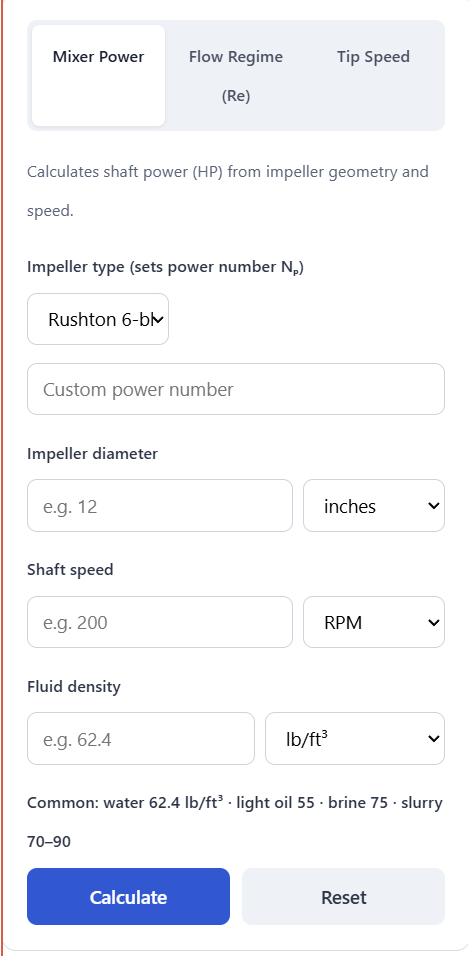
Enter your impeller type, diameter, shaft speed, and fluid density to size the shaft horsepower needed to drive a mixer, or switch tabs to check the Reynolds number and tip speed for the same impeller.
Related Calculators
- All Automotive Calculators
- Fan Horsepower Calculator
- Pump Brake Horsepower Calculator
- Air Motor Horsepower Calculator
Formula
Mixer shaft power (turbulent regime):
P = Np × ρ × N³ × D⁵
where P = power (W), Np = impeller power number, ρ = fluid density (kg/m³), N = shaft speed (rev/s), D = impeller diameter (m). Divide by 745.7 for HP.
Impeller Reynolds number:
Re = ρ × N × D² / μ
where μ = dynamic viscosity (Pa·s).
Tip speed:
v = π × D × N
where v = tip speed (m/s).
Interpretation
The calculated horsepower is the hydraulic power absorbed by the fluid at steady state. Real motors must be sized larger to cover gearbox losses, start-up torque, and process upsets. The power equation P = NpρN³D⁵ only holds when the flow is fully turbulent (Re ≥ 10,000) and Np is constant; at lower Re the power number rises and this equation under-predicts.
- < 0.25 HP — benchtop / lab mixer.
- 0.25–5 HP — pilot-scale and small process tanks.
- 5–50 HP — typical production agitators.
- > 50 HP — large industrial units; verify gearbox service factor.
- Motor sizing — add a 15–25% service factor to calculated shaft power.
Tip speed is the shear proxy. Under ~500 ft/min is gentle (shear-sensitive fluids, polymers, cell culture), 500–2,000 ft/min is a standard blending range, 2,000–4,500 ft/min handles turbulent blending and gas dispersion, and above 4,500 ft/min risks vortexing, cavitation, and shear damage.
Typical Power Numbers (Np) in Turbulent Flow
| Impeller | Np | Primary Action |
|---|---|---|
| Rushton 6-blade turbine | ~5.0 | Radial / gas dispersion |
| Flat-blade paddle | ~4.0 | Radial |
| Pitched-blade turbine, 45° | ~1.3 | Axial / blending |
| Marine propeller, 3-blade | ~0.35 | Axial |
| Anchor impeller | ~0.35 | Viscous / wall sweeping |
| High-efficiency hydrofoil | ~0.30 | Axial / solids suspension |
Values assume a baffled tank with D/T ≈ 0.33. Un-baffled tanks, off-center mounting, or close wall clearances will shift Np significantly.
FAQ
What units should I use for density and viscosity?
Use whatever is convenient — the calculator converts internally. Water is 62.4 lb/ft³ (≈ 1,000 kg/m³, SG 1.0) and 1 cP. For slurries, use the bulk density of the mixture, not the carrier fluid alone.
Does the calculated HP include motor and gearbox losses?
No. This is the power transferred from the impeller to the fluid. Add a 15–25% service factor for the motor, and account for gearbox efficiency (typically 90–97%) when specifying the drive.
Why does my low-viscosity result look too small?
The cube of speed and fifth power of diameter make mixer power extremely sensitive to both. Doubling the impeller diameter multiplies power by 32×. Small geometry changes at design speed move HP dramatically — that is expected, not an error.
Can I use this formula for laminar mixing (high viscosity)?
Not directly. Below Re ≈ 10, power scales as P ∝ μN²D³ rather than ρN³D⁵, and Np is no longer constant. Check the Reynolds tab first; if you are in the laminar or transitional range, use a viscosity-corrected power number from the impeller's published Np–Re curve.