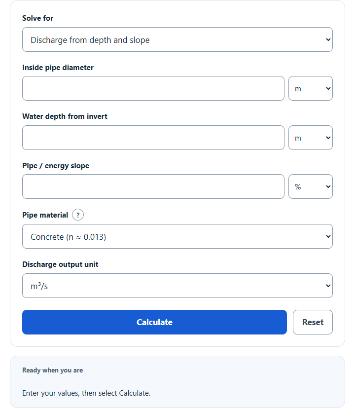
Calculate partially full pipe flow with Manning’s equation: enter diameter, water depth and slope, pick a pipe material, and get discharge and velocity.
Related Calculators
- Parshall Flume Flow Calculator
- Channel Slope Calculator
- Inch Per Foot Slope Calculator
- Slope Per Foot Calculator
- All Construction Calculators
Partial Pipe Flow Formula
A partially filled circular pipe carries liquid through only part of its cross-section. This calculator uses wetted circular-segment geometry and Manning’s equation for steady uniform gravity flow. It solves discharge, required energy slope, or normal depth with an explicit shallow/deep branch. Inputs are converted to SI; velocity is calculated as Q/A rather than assumed to be 1 ft/s.
Variable Definitions
- Q = flow rate
- v = average flow velocity
- A = wetted cross-sectional area
- D = pipe diameter
- r = pipe radius
- θ = wetted central angle
Important: The segment-area equation uses radians. Enter water depth measured from the invert; the calculator derives the angle. It has no angle-entry field. Inside diameter/depth accept m, mm, ft or in; discharge accepts m³/s, L/s, cfs or US gpm. Changing an input unit preserves the physical quantity.
How the Calculator Works
- Convert diameter, depth and discharge to SI, and percent slope to its decimal fraction.
- Derive the wetted angle from the entered depth and diameter.
- Compute the area of the circular segment occupied by the fluid.
- Find wetted perimeter P and hydraulic radius Rh=A/P, then apply Q=A Rh(2/3) √S/n. Pick a pipe material for its typical n (concrete, 0.013, by default) or choose Custom Manning n for your pipe’s condition.
- Convert the result to the selected output unit such as cfs, cms, L/s, or GPM.
Understanding the Wetted Central Angle
The wetted central angle is measured at the center of the pipe between the two points where the liquid surface meets the pipe wall. As the pipe fills, the angle increases from zero to a full circle.
| Fill Condition | Central Angle | Meaning |
|---|---|---|
| Empty | θ = 0 |
No wetted area and no flow. |
| Half Full | θ = π |
The liquid reaches the pipe centerline. |
| Completely Full | θ = 2π |
The entire circular area is filled. |
If You Know Depth Instead of Angle
In field measurements, liquid depth is often easier to observe than the wetted angle. If depth is measured from the invert at the bottom of the pipe, you can convert depth to angle first and then use the main flow equation.
Here, y is the liquid depth. Once the angle is found, substitute it into the segment-area formula to estimate the flow area and discharge.
Example Calculation
Suppose inside diameter is 24 in, water depth 12 in (half full), Manning n=0.013 and slope 1%. Select discharge mode, set both length inputs to inches, and choose cfs output. The calculation converts to SI internally:
This is approximately 11.310580 cfs or 320.279957 L/s, with mean velocity about 7.200539 ft/s. The stated area, roughness and slope—not a fixed velocity—determine discharge.
Practical Notes
- Discharge depends on wetted geometry, slope and Manning roughness. Velocity is Q/A.
- At fixed depth ratio, slope and roughness, Manning discharge scales with diameter(8/3). Area alone scales with diameter squared.
- Wetted area increases nonlinearly with depth; Manning discharge reaches a maximum before the crown and then decreases toward the full-depth reference.
- This tool is useful for quick estimates, comparisons between fill levels, and checking how much of the pipe cross-section is actively carrying flow.
Limits of This Estimate
The model assumes steady uniform free-surface gravity flow with constant n and energy slope equal to pipe slope. It does not solve inlet control, backwater, surcharge or pressure flow. See EPA SWMM Hydraulics, chapters 4–5. Froude number uses hydraulic depth A/T and is unavailable at dry/full-crown endpoints; see the USBR Froude definition. Average shear uses ρgRhS with approximate freshwater density 1000 kg/m³; see the HEC-RAS shear relation. These estimates do not replace a site hydraulic design.
- n = Manning roughness coefficient
- Rh = hydraulic radius
- S = slope
The conventional tabulated n retains its numerical value after dimensional inputs are converted to SI; do not add a US 1.486 coefficient to that SI calculation (USGS FEQUTL, equation 5). Slope inversion uses S=[Qn/(A Rh(2/3))]². Normal-depth inversion has two partial-depth roots only between Qfull and Qmax; the peak is derived near y/D=0.938181, with Qmax/Qfull≈1.075706. At Qfull the deep root is the crown boundary; below Qfull the deep branch is unavailable. Full depth is a limiting gravity-flow reference. Dry discharge is zero. Zero discharge at zero depth cannot determine slope; zero slope and zero discharge cannot determine normal depth. The chosen depth branch does not itself identify subcritical or supercritical flow.