Calculate wind load on a pole or sign from wind speed, exposed height and diameter or projected area, with results in N, lbf and kgf.
Pole Wind Load Formula
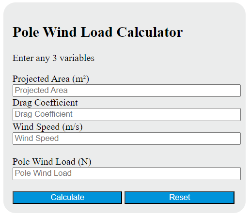
The pole wind load equation estimates the horizontal force created when wind pushes against the pole’s projected area. It is most useful for quick sizing, comparison, and preliminary structural checks.
Variable definitions
- PWL = pole wind load
- A = projected area facing the wind
- Cd = drag coefficient
- V = wind speed
When area is entered in square meters and wind speed is entered in meters per second, the load is returned in newtons. The constant 0.613 represents the standard dynamic pressure relationship for air at typical sea-level conditions.
If you want to compute the same relationship manually with common imperial units, this consistent form is often used:
In that form, area is in square feet, wind speed is in miles per hour, and the result is in pounds-force.
Rearranged Forms
Because the calculator can solve for any one variable, these equivalent forms are helpful when checking area, drag coefficient, or required wind speed.
How to Estimate Projected Area
Projected area is the frontal area seen by the wind, not the total outside surface area of the pole. For a simple round or prismatic pole, the projected area is usually based on width times exposed height.
For a straight pole with uniform diameter or width:
For a tapered pole, a practical first estimate uses the average diameter:
If the pole has fixtures, banners, signs, luminaires, cameras, or other attachments, add their frontal areas to the pole area:
| Shape or condition | Projected area guidance |
|---|---|
| Round pole | Use exposed height multiplied by outside diameter. |
| Tapered pole | Use average diameter multiplied by exposed height for a quick estimate. |
| Square or rectangular pole | Use face width multiplied by exposed height. |
| Pole with accessories | Add the frontal area of each attachment to the pole’s projected area. |
How to Calculate Pole Wind Load
- Measure or estimate the exposed projected area.
- Select a drag coefficient that reasonably matches the pole shape and surface condition.
- Use the relevant wind speed for your check or design scenario.
- Insert the values into the equation.
- Review the result in newtons or pounds-force and confirm that units were consistent.
Example Calculation
Suppose a pole has a projected area of 10 square meters, a drag coefficient of 0.8, and a wind speed of 20 meters per second.
The pole wind load is 1961.6 N, which is approximately 441 lbf. This example also shows why wind speed matters so much: because speed is squared, even a moderate increase in wind speed creates a much larger increase in load.
| Input change | Effect on load |
|---|---|
| Area doubles | Load doubles. |
| Drag coefficient doubles | Load doubles. |
| Wind speed doubles | Load becomes four times larger. |
Choosing a Drag Coefficient
The drag coefficient depends on shape, surface roughness, flow behavior, and whether the member is cylindrical, square, flat, or fitted with accessories. For preliminary estimates, these broad ranges are often useful:
| Geometry | Typical preliminary range | Notes |
|---|---|---|
| Round pole or cylinder | About 0.7 to 1.2 | Common for smooth cylindrical members. |
| Square or rectangular member | About 1.1 to 1.8 | Higher than round sections because of sharper flow separation. |
| Flat plate normal to wind | About 1.8 to 2.0 | Represents a very high-drag surface. |
If your pole supports lights, signs, antennas, or banner arms, the effective load may increase significantly because both frontal area and aerodynamic behavior change.
Approximate Base Moment
If you also need a quick estimate of the overturning moment at the base and the wind load is distributed more or less uniformly over the exposed height, a first-pass approximation is:
This assumes the resultant force acts at mid-height. If the pole is tapered or has large attachments near the top, the true force location may be higher or lower.
Common Mistakes
- Using total surface area instead of projected area.
- Mixing metric and imperial units in the same calculation.
- Ignoring attachments that add frontal area.
- Using an unrealistic drag coefficient for the pole shape.
- Assuming a simplified wind-load estimate is the same as a full structural design check.
When This Calculator Is Most Useful
- Utility poles, light poles, sign poles, and flagpoles
- Comparing alternate diameters, shapes, or accessory layouts
- Estimating how much additional load a fixture adds
- Checking how sensitive the design is to changes in wind speed
- Educational or preliminary engineering calculations
Important Design Note
This calculator is best used for estimation and screening. Real-world pole design may also need to consider gust effects, local exposure, terrain, ice, vibration, deflection limits, connection details, and foundation capacity. If the pole is part of a permanent structure or safety-critical installation, the final design should be verified using the applicable structural design requirements.