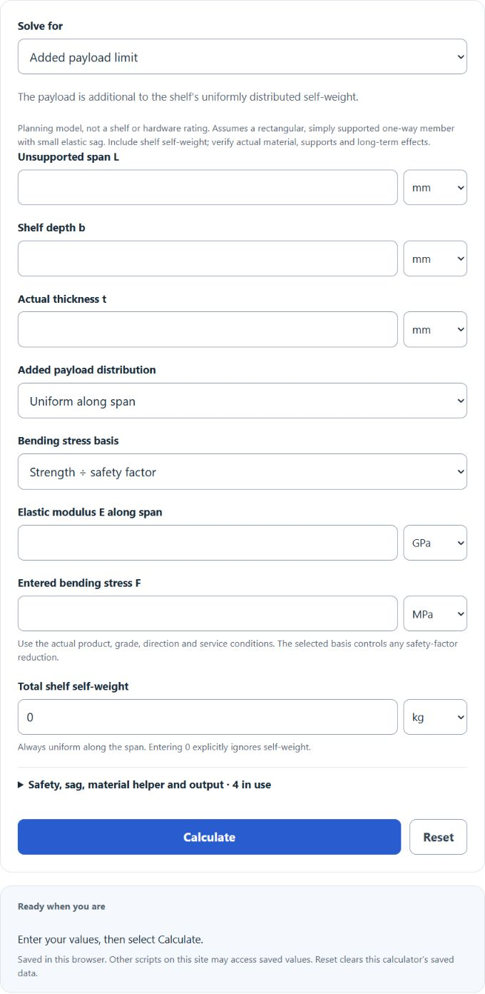
Estimate added payload or check a planned load using a simply supported shelf model, actual dimensions, entered material properties, stress basis, immediate sag limit and shelf self-weight. This calculation is not a rated safe load for the shelf, supports or hardware.
Related Calculators
- Deck Weight Limit Calculator
- Steel Deflection Calculator
- Length to Beam Ratio Calculator
- LVL (Laminated Veneer Lumber) Weight Calculator
- All Construction Calculators
Shelf Load Capacity Formula
For a rectangular simply supported shelf under a uniform total load, the bending-only force limit before deducting self-weight is:
Variables:
- Qb is the uniform bending-limited total force before self-weight deduction (lbf with consistent inch/psi inputs, or N with metre/Pa inputs)
- σlim is the selected bending stress limit: entered reference strength F divided by the selected safety factor, or an already adjusted allowable F used directly without dividing again
- W is shelf depth, front to back (inches, when using psi and lbf)
- T is the shelf thickness (inches)
- L is the unsupported span between simple end supports (inches, when using psi and lbf)
What is Shelf Load Capacity?
An actual shelf rating depends on the member, support system and service conditions. This calculator estimates only bending stress and immediate elastic sag for a rectangular one-way member with simple end supports. It does not rate brackets, fasteners, anchors, joints, shear, local bearing/plate bending, buckling, defects, moisture, impact or long-term creep. The load must act across shelf depth as assumed by a beam model. Verify actual material and hardware; obtain a qualified assessment for safety-critical use.
How to Calculate Shelf Load Capacity?
The following steps outline how to calculate the Shelf Load Capacity:
- First, obtain the actual product/grade/direction elastic modulus E and an appropriate bending stress F in compatible units. Choose reference strength divided by safety factor, or already adjusted allowable stress without a second division. A test strength divided by 2 does not by itself establish a code-compliant design allowable.
- Next, measure the shelf width (W) in inches.
- Measure the shelf thickness (T) in inches.
- Measure the shelf length (L) in inches.
- Use both bending and immediate sag criteria. With I = WT³/12, a uniform total force Q gives M = QL/8 and sag δ = 5QL³/(384EI); a center force P gives M = PL/4 and δ = PL³/(48EI). The center bending-only force limit is (2/3)σlimWT²/L. Set the selected sag limit δlim = L/x and solve each criterion for payload; the lower remaining force governs. AWC Design Aid 6, Figures 1 and 7, gives these simple-beam cases. Shelf self-weight D is always uniform and its DL/8 moment and 5DL³/(384EI) sag must be added separately, even with a center payload. If self-weight alone exceeds a criterion, zero added payload does not pass.
- After inserting the variables and calculating the result, check your answer with the calculator above.
Example Problem:
Use the following hypothetical values to illustrate the model; they are not verified properties or a safe rating for a particular shelf.
Reference bending strength F = 3000 psi; choose safety factor 2, so σlim = 1500 psi. This is an arithmetic assumption, not a manufacturer design allowable.
shelf width (W) = 24 inches
shelf thickness (T) = 1.5 inches
shelf length (L) = 48 inches
Also specify E = 1,000,000 psi, sag limit L/240 = 0.2 in, and self-weight D = 0 lbf for this illustration only. I = 24 × 1.5³/12 = 6.75 in⁴. The uniform bending limit is 2250 lbf, while the immediate sag limit is 937.5 lbf, so the modeled added payload is 937.5 lbf. For a center payload, the bending and sag limits are 1125 lbf and 585.9375 lbf, respectively, so sag again governs. If 3000 psi were already adjusted allowable stress, the uniform bending-only limit would be 4500 lbf without a second safety reduction; the stated sag limit would still govern. Enter actual self-weight for a real shelf: uniform self-weight reduces uniform payload capacity directly, while a center payload must use the separate uniform-load contribution.
The defaults 2 and L/240 are editable planning choices, not universal design requirements. Generic material names do not establish E or strength. The named MEDITE INDUSTRIAL MR helper is only an illustration using the manufacturer’s EN 310 test properties for actual thickness greater than 12 through 19 mm: E = 2.4 GPa and reference modulus of rupture = 24 MPa. These are not design allowables or a shelf/hardware rating. Creep, environment, grade/direction and the actual fixing system require separate assessment; no automatic creep correction is assumed.