Calculate transformer fault current or equivalent impedance from kVA, voltage, %Z, and phase for single-phase or three-phase systems.
- All Physics Calculators
- All Electrical Calculators
- Transformer Calculator
- ZS (Earth Loop Impedance) Calculator
- Transformer Voltage Calculator
- Transformer Efficiency Calculator
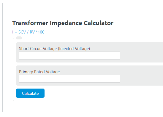
Transformer Impedance Formula
The following formula is used to calculate transformer impedance percentage:
- %Z is the transformer impedance percentage
- VSC is the short-circuit test voltage (volts applied to primary to drive rated current through a bolted secondary short)
- Vrated is the rated primary voltage
To calculate transformer impedance percentage, divide the short-circuit test voltage by the rated voltage and multiply by 100. The result is a dimensionless percentage stamped permanently on the transformer nameplate.
What Transformer Impedance Percentage Represents
Transformer impedance percentage (%Z) is not an absolute ohmic value. It expresses the fraction of rated voltage required to push full-load current through a bolted short on the secondary side. Physically, %Z captures two internal losses: resistive losses from winding conductor resistance (I²R), and reactive losses from leakage flux between primary and secondary windings. These two components separate into resistance R and leakage reactance X, with Z = √(R² + X²) and their ratio X/R having separate consequences for fault analysis.
The short-circuit test procedure that produces this value is straightforward: the secondary winding is bolted short, and the primary voltage is raised from zero until the ammeter reads rated current in both windings. The applied voltage at that exact point, expressed as a percentage of rated voltage, is the transformer’s %Z. Because only a small fraction of rated voltage is needed (typically 4-14%), iron losses are negligible during this test, meaning %Z essentially measures the leakage impedance of the copper circuit alone.
Typical %Z Values by Transformer Rating
The following values reflect industry norms per IEEE C57.12.00 (liquid-immersed) and IEEE C57.12.01 (dry-type). Actual nameplate values vary by manufacturer and cooling class, but these ranges are widely used for fault current screening calculations.
| Transformer Rating | Typical %Z (Dry-Type) | Typical %Z (Oil-Filled) | Typical X/R Ratio |
|---|---|---|---|
| 15-75 kVA | 4.5-5.0% | 3.5-4.5% | 2-4 |
| 100-300 kVA | 5.0-5.75% | 4.0-5.5% | 3-6 |
| 500-1000 kVA | 5.75-6.0% | 5.0-6.0% | 5-8 |
| 1500-2500 kVA | 6.0-6.5% | 5.5-7.0% | 7-12 |
| 3000-10,000 kVA | 6.5-8.0% | 6.0-8.0% | 10-20 |
| 10-100 MVA | N/A (liquid only) | 7.0-12.0% | 15-30 |
| >100 MVA (power) | N/A | 10.0-14.0% | 25-50+ |
Fault Current and Voltage Regulation: The Core Tradeoff
%Z controls two competing system behaviors that pull in opposite directions. The symmetrical short-circuit current available at the transformer secondary is: I₁ᵣᶜ = I₁ᵧᶜ / (%Z/100), or equivalently, I₁ᵣᶜ = I₁ᵧᶜ × (100 / %Z). A 1000 kVA, 480 V transformer with 5%Z has a full-load current of approximately 1203 A and a bolted-fault current of approximately 24,056 A. The same transformer wound to 6%Z produces only about 20,047 A of fault current on the secondary, a 17% reduction, at the cost of somewhat worse voltage regulation.
Voltage regulation under full-load, unity power factor is approximately equal to the resistive component of %Z (the %R portion). Under lagging power factor loads, voltage regulation increases further because the reactive component (%X) adds constructively. This is why specifying a lower %Z for a distribution transformer serving motor loads lowers both fault current protection margin and voltage stability. Designers targeting tight voltage regulation on sensitive loads (data centers, medical equipment) prefer 4-5%Z, while installations with marginal switchgear interrupting ratings benefit from higher 6-8%Z to reduce available fault current.
X/R Ratio and Asymmetrical Fault Current
The total impedance %Z breaks into resistive (R) and reactive (X) components. Their ratio X/R determines how quickly the DC offset component of fault current decays after a short-circuit initiates. At the instant of fault, the total current includes a symmetrical AC component plus a DC transient that peaks at approximately I₁ᵣᶜ × √2 × (1 + e⁻⁽⁹⁾/ₓ⁾⁾) depending on point-on-wave. The DC offset time constant is τ = (X/R) / (2πf). At 60 Hz with X/R = 10, τ = 26.5 ms; at X/R = 20, τ = 53 ms. This has direct consequences for circuit breaker interrupting duty ratings under IEEE C37.010, which derate breaker capability at high X/R.
Small distribution transformers (15-300 kVA) have X/R ratios of 2-6, meaning fault current DC offset decays within two to three cycles. Large power transformers (10+ MVA) typically have X/R of 15-50. When calculating arc flash incident energy per IEEE 1584-2018, ignoring the X/R ratio and using only symmetrical fault current produces a non-conservative result, because the higher peak asymmetrical current increases arc energy during the first few cycles before clearing.
Parallel Transformer Operation and %Z Matching
When two transformers are operated in parallel, load sharing between them is inversely proportional to their per-unit impedances. A unit with lower %Z carries a disproportionately larger share of the total load. For example, a 1000 kVA transformer at 6%Z in parallel with a 500 kVA transformer at 4%Z will cause the smaller, lower-impedance unit to be overloaded at relatively modest combined loads. For proportional load sharing, three conditions must be satisfied: voltage ratios must match within approximately 0.5%, per-unit impedances (both referred to the same MVA base) must be within 7.5% of each other, and winding vector groups must be compatible (e.g., both Dyn11 or both Yyn0). Mismatching any of these conditions forces circulating currents at no-load, reducing effective capacity and increasing copper losses.
IEEE and IEC Manufacturing Tolerances
The nameplate %Z is a guaranteed nominal value, not an exact measurement. IEEE C57.12.00 and C57.12.01 permit a manufacturing tolerance of ±7.5% of the nameplate value for two-winding transformers. IEC 60076-1 allows ±10% for two-winding units and ±10% for auto-transformers and three-winding designs. This means a transformer labeled 6.0%Z could leave the factory anywhere between 5.55% and 6.45% (IEEE) or 5.4% and 6.6% (IEC). For power system fault studies, engineers typically calculate fault current at both the minimum tolerance (highest available fault current) and maximum tolerance (lowest fault current that must still trip protection), bracketing the design to ensure protective devices operate correctly across the full range.
IEC 60076-5 additionally sets minimum short-circuit withstand requirements: the transformer must survive a 2-second through-fault at the calculated short-circuit current without damage. This standard effectively establishes a minimum %Z floor at each rating since very low-impedance designs would produce fault currents exceeding the mechanical withstand of the windings.
Applications in Protection Coordination and Arc Flash
Every fault current calculation for a distribution system begins with the transformer %Z. The available short-circuit current determines the interrupting rating required for all downstream breakers, fuses, and motor starters. NEC Article 110.9 requires that overcurrent devices have an interrupting rating not less than the available fault current at their terminals, a requirement that traces directly back to the transformer %Z and the system source impedance upstream of the transformer.
In arc flash hazard analysis per IEEE 1584-2018, the arcing current is a function of bolted fault current (itself derived from %Z), the gap between conductors, and the working distance. Lowering %Z from 6% to 4% on a 480 V, 1000 kVA transformer increases arc flash incident energy by roughly 30-50% depending on bus configuration and clearing time. This is why some facilities deliberately specify higher-impedance transformers when existing protection settings cannot be tightened, trading voltage regulation headroom for reduced arc flash hazard category. The calculator above includes both symmetrical fault current and motor load contribution outputs specifically to support these upstream protection and hazard calculations.