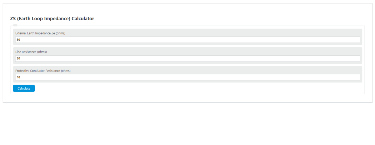
Calculate earth loop impedance Zs from Ze and R1+R2, or check measured Zs against BS 7671 limits for Type B, C or D MCBs by rating.
- All Physics Calculators
- Coax Cable Calculator (Impedance-Inductance-Capacitance)
- Parallel Impedance Calculator
- Transformer Impedance Calculator
ZS (Earth Loop Impedance) Formula
The ZS value represents the total impedance of the earth fault loop at the point of the circuit. In simple terms, it combines the external supply-side earth loop impedance with the resistance of the circuit conductors involved in the fault path. This calculator is useful for quickly estimating or checking the line-earth loop impedance when three of the four values are known.
In this relationship:
| Term | Meaning | Typical Unit | Why It Matters |
|---|---|---|---|
| Zs | Total earth fault loop impedance at the circuit | ohms (Ω) | This is the final value used to judge how easily fault current can flow. |
| Ze | External earth loop impedance | ohms (Ω) | Represents the supply-side contribution before the final circuit conductors are added. |
| R1 | Resistance of the line conductor | ohms (Ω) | Increases with conductor length, temperature, and reduced cross-sectional area. |
| R2 | Resistance of the protective conductor | ohms (Ω) | Forms part of the return path during an earth fault. |
Rearranged Forms
If your calculator is set up to solve for any missing value, the same equation can be rearranged as follows:
As long as three values are known and all are entered in the same unit, the fourth can be determined directly.
How to Calculate ZS
- Determine the external earth loop impedance, Ze.
- Find the line conductor resistance, R1.
- Find the protective conductor resistance, R2.
- Add the conductor resistances together.
- Add that result to Ze to obtain Zs.
Mathematically, the process is simply:
Example Calculation
Assume the following values are known:
- External earth loop impedance, Ze = 0.35 Ω
- Line conductor resistance, R1 = 0.18 Ω
- Protective conductor resistance, R2 = 0.12 Ω
First add the conductor resistances:
Then add that value to the external impedance:
The calculated earth loop impedance is 0.65 Ω.
Why ZS Is Important
Earth loop impedance affects the magnitude of fault current that can flow during a line-to-earth fault. In general, a lower Zs allows higher fault current, which helps protective devices operate more quickly. A higher Zs limits fault current and can make disconnection slower or inadequate if it exceeds the permitted value for the protective device and circuit arrangement.
A common approximation for fault current is:
Where:
- If = prospective earth fault current
- Uo = nominal line-to-earth voltage
- Zs = earth fault loop impedance
This is why even a modest increase in loop impedance can materially reduce available fault current.
What Affects Earth Loop Impedance
- Circuit length: Longer conductors generally increase resistance.
- Conductor size: Smaller conductors have higher resistance.
- Conductor material: Copper and aluminum have different resistivities.
- Temperature: Resistance rises as conductor temperature increases.
- Connection quality: Loose, corroded, or damaged terminations can raise impedance.
- Supply characteristics: The external impedance seen at the origin can vary between installations.
- Parallel earth paths: Measured values may differ from purely calculated values where additional conductive paths exist.
Using the Calculator Correctly
- Enter all values in ohms.
- Do not mix ohms with milliohms unless you convert first.
- Make sure R1 and R2 are separate values, not already summed.
- If you already know the combined conductor resistance, split it properly or calculate the missing term before entering values.
- Keep enough decimal places to avoid rounding errors on low-impedance circuits.
Common Mistakes
- Using an estimated value for Ze without checking whether it matches the actual supply arrangement.
- Entering total loop impedance as both Zs and Ze.
- Forgetting that conductor resistance changes with temperature.
- Confusing R1+R2 with either R1 or R2 alone.
- Assuming a calculated value always matches a measured field result exactly.
Practical Interpretation
The calculator gives a fast analytical value for Zs, but real installations may differ slightly because of operating temperature, contact resistance, meter method, and parallel return paths. Use the result as a design, estimation, or checking tool, and compare the final value against the limits required for the protective device and the installation rules that apply to your project.
If you are troubleshooting or verifying a live electrical installation, a proper loop impedance test and qualified review are still important, because safety depends on actual fault performance rather than calculation alone.