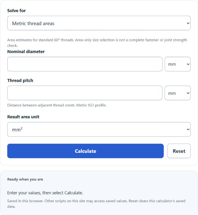
Calculate bolt tensile stress area for standard inch or metric threads, plus plain round shank area, with results in in², mm², and cm².
- All Construction Calculators
- All Area Calculators
- Bolt Length Calculator
- Bolt Pull-Out Force Calculator
- Flange Bolt Torque Calculator
- Bolt Preload Calculator
Bolt Area Formula
The calculator uses one of three formulas depending on the mode you select.
Unified inch threads (tensile stress area):
- At = tensile stress area (in²)
- D = nominal major diameter (in)
- n = threads per inch (TPI)
Metric (ISO) threads (tensile stress area):
- As = tensile stress area (mm²)
- d = nominal major diameter (mm)
- p = thread pitch (mm)
Plain round shank (unthreaded cross-section):
- A = cross-sectional area
- d = bolt or shank diameter
The Unified and ISO formulas approximate the area at the mean of the pitch and minor diameters. They apply to standard 60-degree thread profiles and are the values used in most strength calculations for tensile loading. For threaded shear design, use the area and allowable resistance specified by the governing fastener standard; the calculator’s approximate root area alone does not establish shear capacity.
Reference Tables
Tensile stress areas for common Unified coarse threads:
| Size | D (in) | TPI | At (in²) |
|---|---|---|---|
| 1/4-20 UNC | 0.250 | 20 | 0.0318 |
| 5/16-18 UNC | 0.3125 | 18 | 0.0524 |
| 3/8-16 UNC | 0.375 | 16 | 0.0775 |
| 1/2-13 UNC | 0.500 | 13 | 0.1419 |
| 5/8-11 UNC | 0.625 | 11 | 0.2260 |
| 3/4-10 UNC | 0.750 | 10 | 0.3340 |
| 1-8 UNC | 1.000 | 8 | 0.6060 |
Tensile stress areas for common ISO metric coarse threads:
| Size | d (mm) | p (mm) | As (mm²) |
|---|---|---|---|
| M5 | 5 | 0.8 | 14.2 |
| M6 | 6 | 1.0 | 20.1 |
| M8 | 8 | 1.25 | 36.6 |
| M10 | 10 | 1.5 | 58.0 |
| M12 | 12 | 1.75 | 84.3 |
| M16 | 16 | 2.0 | 157 |
| M20 | 20 | 2.5 | 245 |
| M24 | 24 | 3.0 | 353 |
Worked Example and FAQ
Example: 1/2-13 UNC bolt. D = 0.500 in, n = 13 TPI. Effective diameter = 0.500 − 0.9743/13 = 0.4251 in. At = (π/4) × 0.4251² = 0.1419 in². Multiply by the bolt’s allowable tensile stress to get its working load.
Which area should you use for tensile load? Use the tensile stress area (At or As). The plain shank area overstates capacity because the threads reduce the effective cross-section.
Which area for shear? The location of the shear plane matters. The plain shank and approximate root areas are geometric outputs; use the governing design standard for the appropriate shear resistance and area.
Why 0.9743 and 0.9382? These constants come from the 60-degree thread geometry of Unified and ISO profiles. They place the diameter used in the area formula between the pitch and minor diameters.
Does coating change the area? These nominal area formulas do not model coatings. Coating, corrosion allowance, manufacturing tolerances and surface treatment can affect fit or strength and require separate assessment.