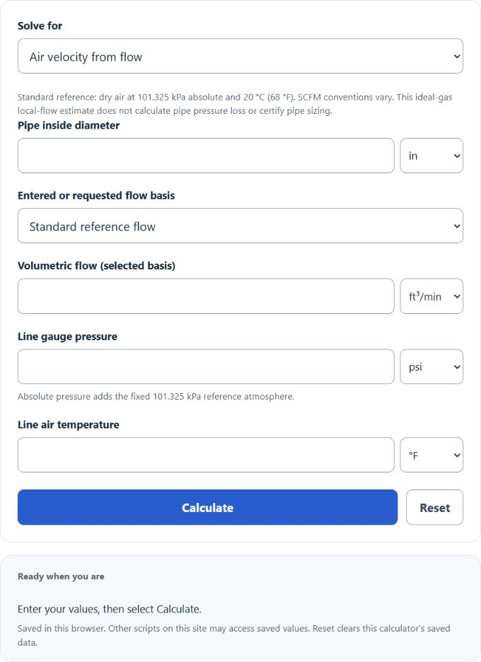
Calculate compressed air velocity or required flow from SCFM or actual flow, pipe inside diameter, line pressure, temperature, and metric or imperial units.
- All Physics Calculators
- All Velocity Calculators
- Wind Velocity Calculator
- Flow to Velocity Calculator
- Compressed Air Temperature Calculator
Compressed Air Velocity Formula
The calculator solves mean velocity from flow or required flow from a velocity target, using either the stated standard reference or actual line flow.
Standard flow and pipe size. Convert standard flow to actual flow at line conditions, then divide by pipe area.
Actual flow and pipe size.
Derived dynamic pressure. This is an output, not an input mode, and is not pipe friction loss.
- V = air velocity (ft/s or m/s)
- SCFM = standard cubic feet per minute (at 14.696 psia, 68°F)
- Q_actual = actual volumetric flow at line conditions (CFM)
- P_abs = absolute line pressure (psia or Pa)
- T = absolute line temperature (°R or K)
- A = pipe cross-sectional area = π × D² / 4 (ft²)
- ΔP = velocity pressure (Pa)
- ρ = air density (kg/m³)
- R_air = 287.05 J/(kg·K)
This calculator’s dry-air reference is 101.325 kPa absolute (approximately 14.696 psia) and 20 °C (68 °F). SCFM references vary; match your supplier’s conditions. Air is modeled as an ideal gas without humidity or real-gas corrections. Accuracy depends on actual conditions, not a universal pressure cutoff.
Reference Tables
The velocity rows below are illustrative planning context, not pipe acceptance criteria. KAESER’s SmartPipe+ guidance uses a maximum main-header reference of 30 ft/s. Confirm allowable pressure loss, pipe dimensions and application-specific limits with the manufacturer.
| Velocity (ft/s) | Typical use | Notes |
|---|---|---|
| Under 15 | Lower velocity | Pressure loss and cost still require evaluation. |
| 20–30 | Main-header reference | Illustrative band; KAESER cites a 30 ft/s main-header maximum. |
| 30–50 | Branch lines, drops | Requires application-specific pressure-loss analysis. |
| Over 50 | Higher velocity | Check noise, loss and moisture transport; velocity alone does not size pipe. |
| Sch 40 pipe | ID (in) | Calculated SCFM at 30 ft/s, 100 psig, 68°F |
|---|---|---|
| 1/2 in | 0.622 | ~30 |
| 3/4 in | 0.824 | ~52 |
| 1 in | 1.049 | ~84 |
| 1 1/2 in | 1.610 | ~199 |
| 2 in | 2.067 | ~327 |
| 3 in | 3.068 | ~721 |
| 4 in | 4.026 | ~1,242 |
Worked Example
You have 100 SCFM flowing through 1 in Sch 40 pipe (ID 1.049 in) at 100 psig and 68°F.
- Pipe area: A = π × (1.049/12)² / 4 ≈ 0.0060018 ft².
- Reference-to-line absolute pressure ratio ≈ 0.1281296.
- Actual flow ≈ 100 × 0.1281296 = 12.8130 ACFM.
- Velocity ≈ 12.8130 / 0.0060018 / 60 = 35.5811 ft/s (10.8451 m/s).
This exceeds the illustrative 30 ft/s main-header reference. A larger inside diameter lowers local velocity, but selecting a pipe requires pressure-loss and equipment checks.
Why velocity matters
Velocity affects friction losses, fitting losses and condensate transport. No fixed velocity band guarantees a pressure drop per 100 ft; length, inside diameter, roughness, fittings, pressure and flow must also be evaluated. See KAESER’s pipe pressure-drop calculator for a separate design calculation.