Calculate the equivalent impedance of two speakers in series or parallel from each speaker’s impedance in ohms or kilohms and choose output units.
- All Physics Calculators
- Inductor Impedance Calculator
- Sound Pressure Level Calculator
- Port Length Calculator
- Subwoofer Cone Area Calculator
- Acoustic Impedance Calculator
- Speaker Voltage Calculator
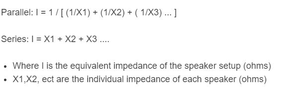
Speaker Impedance Formula
- Z = total equivalent impedance of the speaker system (ohms)
- Z1, Z2, Z3… = impedance of each individual speaker (ohms)
- Zn = impedance of any one speaker (ohms, when all are equal)
- n = number of identical speakers wired in parallel
Common Wiring Configurations
The table below shows the resulting impedance for common configurations using identical 8 Ω speakers.
| Configuration | Formula | 2x 8 Ω | 4x 8 Ω |
|---|---|---|---|
| All Series | Z1 + Z2 + … | 16 Ω | 32 Ω |
| All Parallel | Zn / n | 4 Ω | 2 Ω |
| Series-Parallel (2+2 pairs) | (Z1+Z2) in parallel with (Z3+Z4) | N/A | 8 Ω |
| Parallel-Series (2 parallel pairs in series) | (Z1||Z2) + (Z3||Z4) | N/A | 8 Ω |
Amplifier Minimum Load by Type
Use the permitted speaker load for your exact amplifier model, operating mode and output connection. The figures below are illustrative examples only; amplifier categories do not establish a safe minimum.
| Amplifier Type | Example Load | Note |
|---|---|---|
| Hi-fi stereo amp | 4 Ω | Check the exact model manual |
| AV receiver | 6 Ω | Zone outputs may have different requirements |
| Car audio (stereo mode) | 4 Ω | Bridged operation has model-specific load limits |
| Car audio (mono / sub amp) | 2 Ω | Check the specified load and operating mode |
| Guitar or bass amp | 4 Ω | Some are transformer-coupled; follow specified matching requirements |
| Pro power amp | 4 Ω | Check the specified load and cooling requirements |
Nominal vs. Minimum Impedance
Speaker impedance varies with frequency and includes resistance and reactance. A nominal impedance is a single-number rating; it does not give the full impedance curve or certify compatibility with an amplifier. The 80% figures below are arithmetic reference examples, not measurements or a compliance assessment. Use the manufacturer’s minimum-impedance specification and frequency curve.
| Nominal Rating | 80% of Nominal (arithmetic) | Actual Minimum | DC Resistance |
|---|---|---|---|
| 4 Ω | 3.2 Ω | Model-specific | Measure or check specification |
| 6 Ω | 4.8 Ω | Model-specific | Measure or check specification |
| 8 Ω | 6.4 Ω | Model-specific | Model-specific |
| 16 Ω | 12.8 Ω | Model-specific | Model-specific |
Impedance and Power Output
For a purely resistive model, average power is P = V² / R using RMS voltage. Halving resistance at a fixed voltage doubles model power. Real speaker power also depends on complex impedance, frequency and amplifier limits. The table uses an ideal resistive load and 28 V RMS:
| Speaker Load | Power at 28 V | Relative to 4 Ω Load | Amp Risk |
|---|---|---|---|
| 16 Ω | 49 W | 25% | Check amplifier rating |
| 8 Ω | 98 W | 50% | Check amplifier rating |
| 4 Ω | 196 W | 100% (reference) | Check amplifier rating |
| 2 Ω | 392 W | 200% | High if amp not rated for 2 Ω |
How to calculate speaker impedance?
Example Problem:
First, determine whether the speaker is in parallel or series. For this example, two speakers are in parallel.
Next, determine the impedance of each individual component. For this problem, both nominal impedances are 8 ohms.
Finally, calculate the speaker impedance using the formula above:
Parallel: Z = 1 / (1/Z1 + 1/Z2)
Parallel: Z = 1 / (1/8 + 1/8)
Parallel: Z = 4 ohms
FAQ
Impedance affects power delivery, not volume directly. In an ideal resistive model at fixed RMS voltage, a lower resistance draws more power (P = V²/R). Real power and loudness depend on the amplifier, impedance curve and speaker sensitivity. The key issue is whether total system impedance falls within the amplifier’s rated range.
Yes. Speakers with different impedances can be wired in series or parallel, and the standard formulas apply. The resulting total impedance must fall within the amplifier’s rated range. In parallel configurations, the lower-impedance speaker will receive more power than the higher-impedance one, creating unequal power delivery; relative loudness also depends on speaker sensitivity and frequency response.
A dual voice coil speaker has two separate voice coils with independent impedance ratings (e.g., 4 Ω + 4 Ω). Wiring the coils in series produces twice the rated coil impedance (8 Ω). Wiring them in parallel produces half (2 Ω). This flexibility is common in car audio subwoofer installations: a single DVC 4 Ω sub wired in parallel presents a 2 Ω load, which is suitable only when the particular amplifier permits that load.
Disconnect the speaker from all circuits. Set a multimeter to resistance (Ω) mode and measure across the speaker terminals. This is DC resistance, not nominal audio-frequency impedance. The relationship is model-specific; compare the result with the manufacturer’s specification. For a full impedance vs. frequency curve, an audio impedance analyzer (such as the Dayton Audio DATS) is required.