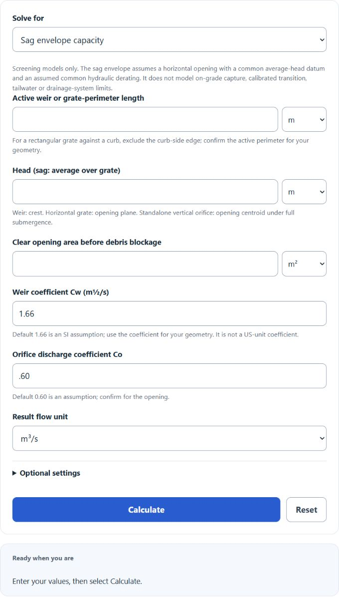
Estimate grate inlet capacity in a sag from the grate perimeter, ponded head and clear opening area using weir and orifice flow, with a blockage allowance.
- All Construction Calculators
- Flow Rate Pressure Calculator
- Water Flow Rate Calculator
- Manning’s Flow Calculator
- TFA – Total Flow Area Calculator
- Self-Cleansing Velocity Calculator
- Overflow Flow Rate Calculator
Inlet Capacity Formula
The equation below describes a fully submerged opening. Use head above the opening centroid for a vertical orifice; for a horizontal grate, use the applicable head over its plane. The calculator also preserves standalone weir flow, rational peak runoff and a simplified horizontal sag-grate envelope. The envelope is not a calibrated transition law or an on-grade interception model.
- Where Q is the inlet capacity (m3/s)
- C is a dimensionless orifice discharge coefficient; 0.67 is used in this example, not a universal value.
- A is the inlet opening area (m2)
- g is the acceleration due to gravity
- H is head in metres relative to the appropriate opening datum, under the equation’s submergence assumptions
For a submerged opening, Q = Co A √(2gh). The weir relation is Qw = Cw L h(3/2), with Cw entered in SI m½/s even when dimensions use feet or inches. The sag screening envelope is F × min(Qw,Qo), where F is the assumed common hydraulic derating. Real debris reduces opening area and effective perimeter differently; this common factor is only an explicit sensitivity assumption. Confirm coefficients, active perimeter, head datum, transition, tailwater and downstream limits using the FHWA HEC-22 Urban Drainage Design Manual.
Curb-opening inlet in a sag
The curb-opening mode estimates flow through an undepressed rectangular curb opening with a horizontal throat, as shown in Figure 7.17(a) of the FHWA HEC-22 Urban Drainage Design Manual, fourth edition. Enter the clear opening length L, vertical opening height h, and ponded water depth d above the sill. This geometry has a vertical opening face; it is different from the manual’s vertical-throat configuration.
For d ≤ h, Qw = 0.37 × √(2g) × L × d1.5. For d ≥ 1.4h, Qo = 0.67 × L × h × √[2g(d − h/2)]. The calculation converts dimensions to metres and uses g = 9.81 m/s², then converts the result to the selected flow unit. These typical coefficients differ from the SI coefficient entered in the existing grate-envelope modes.
Between h and 1.4h, the result identifies the transition zone and shows both equation estimates. They are not a certified range or a calibrated transition capacity. The orifice equation is not applied to a partially submerged opening. The mode assumes an unobstructed opening and free discharge; local depression, on-grade interception, other throat shapes, tailwater and downstream restrictions require the applicable design method.
For example, L = 2.5 m, h = 0.13 m and d = 0.05 m gives weir flow of about 0.04581 m³/s (45.81 L/s). Keep the existing sag-envelope mode for the grate calculation; the curb-opening mode is a separate secondary calculation.
What is an Inlet Capacity?
Definition:
An inlet capacity is a measure of the volumetric flow rate of water the inlet to a water drain can handle.
How to Calculate Inlet Capacity?
Example Problem:
The following example outlines the steps and information needed to calculate Inlet Capacity.
First, determine the orifice coefficient. In this example, this is found to be .67.
Next, determine the clear opening area. This is measured to be 2 m2.
Next, determine the allowable head. This drain system has an allowable head of 3m.
Finally, calculate the inlet capacity using the formula above:
Q = C * A * √(2*g*H)
Q = .67 * 2 * √(2*9.80665*3)
Q ≈ 10.279 m³/s with standard gravity 9.80665 m/s². This standalone-orifice example uses zero derating. Rational-method runoff uses Q = C i A with rainfall converted to m/s and area to m²; choose an applicable design intensity and catchment time of concentration under local guidance.