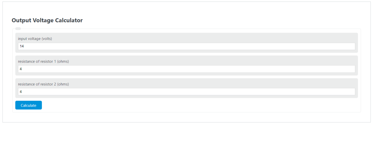
Calculate output voltage, input voltage, or resistor values for a voltage divider circuit by entering any three of Vin, R1, R2, and Vout.
- All Physics Calculators
- All Electrical Calculators
- Attenuation Calculator
- Parallel Voltage Calculator
- Voltage Divider Calculator
- Thevenin Voltage Calculator
Output Voltage Formula
In a two-resistor voltage divider, the output voltage is the portion of the input voltage that appears across R1. This calculator uses the divider form where the output is measured across resistor 1.
- Vo = output voltage across R1
- Vi = input voltage supplied to the divider
- R1 = resistor across which the output is measured
- R2 = the other series resistor in the divider
The equation shows that output voltage depends on the ratio of the resistors, not just their individual values. As R1 becomes a larger share of the total resistance, the output voltage increases. As R2 becomes larger relative to R1, the output voltage decreases.
How to Calculate Output Voltage
- Enter the input voltage.
- Enter the values for R1 and R2 using the same resistance unit.
- Add the two resistances to get the total series resistance.
- Divide R1 by the total resistance to find the divider ratio.
- Multiply that ratio by the input voltage.
This ratio makes quick estimation easy. If R1 is one-half of the total resistance, the output is one-half of the input. If R1 is one-fourth of the total resistance, the output is one-fourth of the input.
Rearranged Forms
If you know any three values, the relationship can be rearranged to solve for the missing one.
Solve for Input Voltage
Solve for R1
Solve for R2
For a passive divider with positive resistor values, the output across R1 must be greater than 0 and less than the input voltage.
Example
If the input voltage is 12 V, R1 is 3 kΩ, and R2 is 9 kΩ, the output voltage across R1 is:
If the two resistors are equal, the output is exactly half of the input:
Practical Notes
- Keep resistance units consistent: Use ohms with ohms, kiloohms with kiloohms, or megaohms with megaohms.
- The output cannot exceed the input in a passive divider: a divider reduces voltage; it does not amplify it.
- Component tolerance matters: real resistors have tolerances, so measured output may differ slightly from the ideal calculation.
- Very small resistor values draw more current: the voltage ratio may be correct, but power loss and heating increase as total resistance decreases.
- Very large resistor values reduce current draw: this is often useful, but extremely high values can make the circuit more sensitive to leakage and loading.
Loaded Divider Adjustment
The basic formula assumes the output is not significantly loaded by another component. If a load resistor is connected across the output, first combine it with R1 as a parallel equivalent, then use that equivalent value in the divider equation.
This is important because a connected load lowers the effective output-side resistance, which usually lowers the actual output voltage compared to the ideal no-load value.
Common Checks
- If R1 and R2 are equal, the output is 50% of the input.
- If R1 is much larger than R2, the output approaches the input voltage.
- If R1 is much smaller than R2, the output becomes a small fraction of the input.
- If R2 is zero, the full input appears across R1.
If Your Output Is Measured Across R2 Instead
Some circuit diagrams define the output across the other resistor. If that matches your setup, use the alternate divider form below or swap the resistor labels before using the calculator.
Common Applications
- Reducing a higher source voltage to a lower reference voltage
- Biasing transistor and amplifier inputs
- Scaling signals for analog-to-digital converters
- Creating sensor reference levels and threshold voltages
- Building simple adjustable voltage networks with resistor changes