Calculate pipe or vessel purge time and required gas flow from internal volume, pipe dimensions, concentration targets, volume changes, and purge effectiveness.
- All Construction Calculators
- Gas Purge Calculator
- CFM to Static Pressure Calculator
- CFM Per Ton Calculator
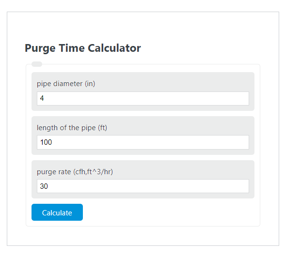
Purge Time Formula
Purge time is the duration required to displace the existing atmosphere inside a pipe with an inert or shielding gas. The core formula treats the pipe interior as a cylinder and divides its volume by the gas flow rate:
Where:
- PT = purge time (minutes)
- V = internal pipe volume (ft³), calculated as V = (pi/4) x (D/12)² x L
- Q = purge flow rate (ft³/min)
- D = internal pipe diameter (inches)
- L = pipe length (feet)
This formula calculates one volume exchange. In practice, a single exchange is rarely sufficient to reduce oxygen to acceptable levels, so the total purge time is multiplied by the number of required volume exchanges (see below).
Volume Exchanges and Industry Standards
A volume exchange represents one complete replacement of the gas inside the pipe. The number of exchanges needed depends on the application, how well the system is sealed, and the target oxygen concentration. Higher exchange counts account for turbulent mixing between the purge gas and residual air, which prevents a perfect piston-like displacement in real systems.
Typical volume exchange requirements by application:
| Application | Volume Exchanges | Target O₂ Level |
|---|---|---|
| Quick field weld estimate | 1 | Visual check only |
| General best practice (NCPWB) | 5 | < 1% |
| Stainless steel / alloy welding | 6 | < 0.5% |
| Gas pipeline purging (displacement) | 2x minimum calculated time | Per operator spec |
| Pharmaceutical / semiconductor piping | 10+ | < 10 ppm |
To get total purge time for a multi-exchange purge, multiply the single-exchange time from the calculator by the number of volume exchanges: Total PT = PT x N, where N is the number of exchanges.
Purge Gas Selection
The choice of purge gas affects cost, flow behavior, and weld quality. Each gas has distinct physical properties that influence how it fills and displaces air in a pipe system.
| Gas | Density vs. Air | Cost (Relative) | Best For | Key Limitation |
|---|---|---|---|---|
| Argon (Ar) | 1.38x heavier | Medium | Stainless steel, titanium, nickel alloy welding | Settles in low points; slower to displace from overhead sections |
| Nitrogen (N₂) | 0.97x (near equal) | Low | Carbon steel purging, pipeline commissioning, system inerting | Reactive at arc temperatures; not for shielding during welding itself |
| Helium (He) | 0.14x lighter | High | Thick-wall pipe, high-heat applications, copper alloys | Requires higher flow rates; must introduce from top of cavity |
| Ar/He mix (75/25) | ~1.1x heavier | Medium-High | Heavy wall stainless, duplex steels | Higher cost than pure argon |
Because argon is heavier than air, it should be introduced at the lowest point of the pipe and allowed to push air upward and out through a vent at the highest point. Helium requires the opposite approach: introduce it at the top and vent from the bottom. Nitrogen, being nearly the same density as air, mixes more readily and depends on flow velocity rather than gravity for displacement.
Purging Methods
There are four recognized methods for purging pipe systems and vessels. Each method suits different geometries, pressure ratings, and operational constraints.
Displacement (Sweep-Through) Purging is the most common method for pipe systems. Inert gas enters at one end and pushes the existing atmosphere out the other. It works best in simple, linear pipe runs where the gas can flow in a uniform front. This is the method the calculator above is designed for. Effectiveness depends on maintaining laminar or near-laminar flow to minimize mixing between the purge gas and residual air.
Dilution Purging introduces inert gas into a vessel or pipe system and allows it to mix with the existing atmosphere, gradually reducing oxygen concentration. The relationship is logarithmic: the volume of purge gas needed equals V x ln(C_initial / C_target), where V is the system volume, C_initial is the starting oxygen concentration (typically 20.9%), and C_target is the desired final concentration. Dilution purging is less gas-efficient than displacement but is practical for complex geometries with dead legs, branches, and irregular cross-sections where a clean sweep is not possible.
Pressure Cycle Purging alternates between pressurizing the system with inert gas and venting it to atmosphere. Each cycle reduces oxygen by the ratio of vent pressure to pressurized pressure. For example, pressurizing to 3 atm and venting to 1 atm reduces oxygen by a factor of 3 per cycle. Starting from 20.9% O₂ and targeting 2%, the minimum number of cycles is ln(20.9/2) / ln(3) = 2.14, meaning 3 cycles are needed. This method is useful for pressure-rated vessels and systems where throughflow is restricted.
Vacuum Purging evacuates the system to low pressure, then backfills with inert gas. Each vacuum/backfill cycle reduces oxygen by the ratio of vacuum pressure to atmospheric pressure. It consumes less total gas than other methods but requires vacuum-rated equipment and is limited to systems that can withstand sub-atmospheric pressures without collapsing.
Recommended Purge Flow Rates
Flow rate selection is critical because too much flow creates turbulence that mixes purge gas with air, actually increasing purge time rather than reducing it. Too little flow allows back-diffusion of oxygen into the purged zone.
| Phase | Flow Rate | Purpose |
|---|---|---|
| Pre-purge (initial fill) | 30 to 50 CFH | Displace bulk atmosphere quickly |
| Welding purge (active welding) | 8 to 15 CFH | Maintain low O₂ without turbulence at the weld root |
| Post-purge (cooling) | 5 to 10 CFH | Protect cooling weld metal from oxidation |
A general guideline from the Huntingdon Fusion Techniques literature suggests 20 L/min (approximately 42 CFH) for pre-purge with about 5 volume changes. After the oxygen analyzer reads below the threshold, the flow rate should be reduced to welding levels. Higher torch-side shielding gas flow is a common mistake that can pull oxygen into the weld zone through the venturi effect.
Pipe Volume Reference Data (Schedule 40)
The table below lists internal volumes per linear foot for standard Schedule 40 pipe sizes. These values allow quick manual estimation of purge time when combined with a known flow rate.
| NPS (in) | Internal Diameter (in) | Volume per Foot (ft³/ft) | Volume per Foot (in³/ft) |
|---|---|---|---|
| 0.5 | 0.622 | 0.00211 | 3.645 |
| 1 | 1.049 | 0.00600 | 10.366 |
| 2 | 2.067 | 0.02330 | 40.257 |
| 3 | 3.068 | 0.05130 | 88.660 |
| 4 | 4.026 | 0.08840 | 152.740 |
| 6 | 6.065 | 0.20060 | 346.590 |
| 8 | 7.981 | 0.34720 | 599.870 |
| 10 | 10.020 | 0.54740 | 945.870 |
| 12 | 11.938 | 0.77700 | 1342.540 |
For example, a 4-inch Schedule 40 pipe that is 200 feet long has an internal volume of 0.0884 x 200 = 17.68 ft³. At a pre-purge rate of 50 CFH (0.833 CFM), a single volume exchange takes 17.68 / 0.833 = 21.2 minutes. For 5 volume exchanges, the total pre-purge time is approximately 106 minutes.
Factors That Increase Purge Time
Calculated purge time represents an ideal case. Several real-world factors add time to the process. Leaks at joints, fittings, or dam seals allow oxygen to re-enter the system and are the most common cause of purge failure. Dead legs, tees, and branch connections create pockets where air is trapped and not displaced by the main flow path. Vertical pipe runs with heavy gases like argon can create stratification issues if the gas is introduced from the wrong end. Valves and fittings add volume that is not accounted for in a straight-pipe calculation, typically adding 5% to 15% to the effective pipe volume depending on the number of fittings.
Temperature also affects purge time. Hot pipe systems cause the purge gas to expand, reducing its effective density and displacement efficiency. For every 100°F increase above ambient, gas volume increases by roughly 10%, which can require proportionally more gas to achieve the same oxygen displacement.
Oxygen Verification
Purge time calculations provide an estimate, but verification with an oxygen analyzer is the only reliable way to confirm the purge is complete. Target oxygen levels vary by material and code. For stainless steel welding, most procedures require oxygen below 0.5% (5,000 ppm) before striking an arc, though many fabricators target below 500 ppm for critical applications. Nickel alloys such as Inconel and Hastelloy typically require below 100 ppm. Carbon steel is more forgiving, with acceptable levels often at or below 1% to 2%. The analyzer probe should be placed at the vent outlet and at the weld joint location, as oxygen levels can vary significantly along the pipe length.