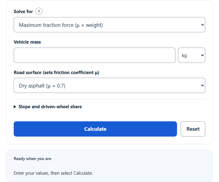
Calculate tractive force: maximum traction from vehicle weight and road surface friction, or the wheel force needed to accelerate and climb grades.
- All Automotive Calculators
- All Force Calculators
- Wheel Horsepower Calculator
- Horsepower to Force Calculator
- Moving Force Calculator
- Energy Loss From Friction Calculator
Tractive Force Formula
Required wheel force is acceleration force plus the selected road loads. The adhesion ceiling is a separate limit, not the force required to drive.
- Where Frequired is the signed required wheel force (N), a is target acceleration, Crr is rolling resistance, and rho, Cd, A and v define aerodynamic drag
- mu is the tire-road adhesion coefficient used only in the optional grip check
- m is the mass of the vehicle (kg)
- g is the acceleration due to gravity (m/s2)
For moving forward, sum acceleration, grade, rolling and aerodynamic terms. At standstill the modeled rolling term is zero. With grade percent =100 tan(theta), the simplified propulsion grip limit is mu × driven normal-load share × m g cos(theta). Acceleration before this limit is explicitly uncapped; negative wheel force does not establish actual braking capacity.
What is a Tractive Force?
Definition:
In mechanics, the tractive force is the component of a force vector parallel to the ground that is applied to a body to cause it to move in the desired direction. Tractive force is also commonly used synonymously with traction force.
How to Calculate Tractive Force?
Example Problem:
The following example calculates an adhesion ceiling, separate from required wheel force.
First, determine the mass of the vehicle. In this example, the vehicle weighs 950 kg.
Assume a tire-road adhesion coefficient of0.7 for this example; this is not a universal tire-road average. Assume level ground and100%of normal load on the driven wheels.
The estimated propulsion-grip ceiling is then:
Fgrip = mu × driven share × m × g
Fgrip =0.7 ×1 ×950 ×9.80665
Fgrip =6521.42225N. Required force still depends on target acceleration and selected road loads; load transfer, actual tire slip and braking distribution are not modeled.