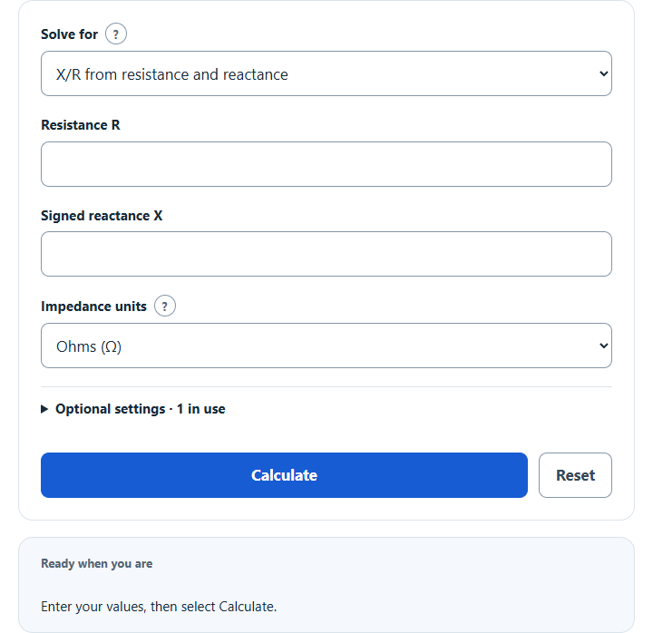
Calculate the X/R ratio from resistance and reactance, or a transformer’s X/R from its MVA rating, impedance % and copper loss, plus impedance and angle.
Related Calculators
- Step-Down Voltage Calculator
- Amp Loss Over Distance Calculator
- HP to Current Calculator
- Line to Phase Current Calculator
- All Physics Calculators
X/R Ratio Formula
The primary magnitude ratio is |X|/R using resistance and reactance on the same basis. Direct mode retains the sign of X for angle and capacitive/inductive interpretation; missing-component modes infer a nonnegative magnitude.
- Where X/R is the X/R ratio
- X is the signed total reactance; |X| is its magnitude.
- R is the positive total resistance in direct mode.
Divide reactance magnitude by resistance. For |Z| and one known component, use |Z|² = R² + X² to solve the missing magnitude. At zero resistance in a missing-component result, X/R is an infinite ideal limit.
What Is an X/R Ratio?
Definition:
X/R compares reactance magnitude with resistance. For an inductive series R–L equivalent, τ = (X/R)/(2πf). Capacitive X does not supply an inductive decay or first-peak estimate. R/|Z| describes the series impedance and is not necessarily the operating load power factor. The fully-offset half-cycle factor is an approximation, not an IEC/IEEE equipment rating check.
How to Calculate X/R Ratio?
Example Problem:
The following example outlines the steps and information needed to calculate X/R Ratio.
First, determine the total reactance. In this example, the reactance is measured to be 50 ohms.
Next, determine the total resistance. For this system, the resistance is calculated to be 40 ohms.
Finally, calculate the X/R Ratio using the formula above:
X/R Ratio = |X|/R
X/R Ratio = 50/40
X/R Ratio = 1.25
For the transformer equivalent, Z(p.u.) = nameplate % / 100, R(p.u.) = full-load load loss(kW) / (1,000 × rated MVA), and X(p.u.) = √(Z² − R²). The three-phase base impedance is line-to-line winding kV² / total MVA. Use consistent rating and test conditions; do not substitute no-load/core loss.
Sources: Eaton Power Distribution Systems, §§1.4-3 and 1.4-17; Wiley/IEEE power-system base quantities, Eq. 1.2; SEL circuit-breaker application paper, Eq. 4.