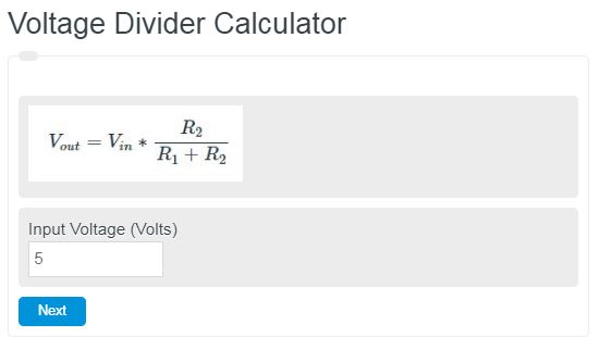
Enter the source voltage and the resistance of two different resistors to calculate the output voltage of a voltage divider.
- All Electrical Calculators
- Ohm’s Law Calculator
- Resistor Divider Calculator
- RMS Voltage (VRMS) Calculator
- Peak Voltage Calculator
- Parallel Voltage Calculator
- Output Voltage Calculator
Voltage Divider Formula
The following formula is used in voltage dividers.
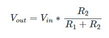
- Where V out is the output voltage
- V in is the input voltage
- R1 is the value of resistor one in resistance
- R2 is the value of resistor two in the resistance
The voltage is measure in volts and the resistance is measure in ohms.
Voltage Divider Definition
A voltage divider is a system or two more resistors that divides an input voltage into a reduced output voltage.
How to calculate a voltage
- First, determine the two resistances.
This is calculating the voltage out in a voltage divider, so there should be two different resistances.
- Next, measure the voltage going into the voltage divider.
Using a voltmeter or similar device, measure the voltage entering the divider.
- Calculate the output voltage.
Enter the information from steps 1 and 2 into the calculator or formula above.
FAQ
How do you choose the right resistors for a voltage divider?
The choice of resistors in a voltage divider depends on the desired output voltage and the current that will flow through the circuit. It’s important to select resistors that can handle the power without overheating. The values of the resistors should be chosen based on the formula (V_{out} = V_{in} times frac{R2}{R1 + R2}) to achieve the required output voltage.
Can a voltage divider be used to step up voltage?
No, a voltage divider is designed to step down or reduce the input voltage to a lower output voltage. To step up voltage, a different type of circuit, such as a boost converter, is required.
Is it possible to use a voltage divider with AC signals?
Yes, voltage dividers can be used with both DC and AC signals. However, when working with AC signals, the impedance of the resistors (or other components, if capacitors or inductors are used) must be taken into account, as it can affect the output voltage differently than in DC circuits.