Calculate the angle between two bearings or azimuths, convert quadrant bearings and find bearings from coordinates or projected points.
Related Calculators
- Arctan Calculator
- Polar Coordinates Calculator
- Radial Distance Calculator
- Average Slope Calculator
- All Math and Numbers Calculators
Angle Between Bearings Formula
The main angle-between calculation compares two bearings or azimuths after converting them to degrees and normalizing them to the range 0° to 360°.
- B1 = first bearing or azimuth, in degrees after conversion if needed
- B2 = second bearing or azimuth, in degrees after conversion if needed
- CW = clockwise angle from bearing 1 to bearing 2
- CCW = counterclockwise angle from bearing 1 to bearing 2
- A = smaller angle between the bearings
- E = exterior angle
For radians, the calculator uses this conversion before or after the bearing calculation:
For quadrant bearing conversion, the azimuth depends on the starting direction, the angle, and the ending direction.
- theta = quadrant bearing angle, from 0° to 90°
- AZ = azimuth measured clockwise from north
For back azimuths and magnetic declination conversions, the calculator uses:
- BAZ = back azimuth
- Declination = magnetic declination, with east positive and west negative
For a bearing from coordinates, the calculator finds the change in easting and northing, then uses atan2 with east first and north second so that 0° points north.
- E1, N1 = starting easting/X and northing/Y
- E2, N2 = ending easting/X and northing/Y
- dE = change in easting or X
- dN = change in northing or Y
- D = straight-line distance between the two points
For projecting a point from a start coordinate, distance, and azimuth, the calculator uses:
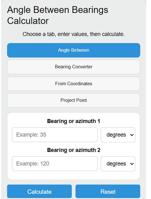
The angle-between tab returns the smaller angle, clockwise angle, counterclockwise angle, exterior angle, line angle, and smaller-angle bisector. The converter tab changes between azimuths, quadrant bearings, back bearings, and magnetic or true bearings. The coordinate tab calculates bearing and distance from two points. The project point tab calculates the endpoint from a starting point, distance, and azimuth.
Bearing and Azimuth Reference Tables
Use these tables to check common direction conventions and interpret the calculator output.
| Direction | Azimuth | Quadrant bearing form |
|---|---|---|
| North | 0° or 360° | N 0° E |
| East | 90° | N 90° E |
| South | 180° | S 0° E |
| West | 270° | S 90° W |
| Azimuth range | Quadrant | Quadrant bearing angle |
|---|---|---|
| 0° to 90° | NE | N azimuth E |
| 90° to 180° | SE | S (180° - azimuth) E |
| 180° to 270° | SW | S (azimuth - 180°) W |
| 270° to 360° | NW | N (360° - azimuth) W |
Example Problems
Example 1: Find the smaller angle between two bearings
Suppose bearing 1 is 35° and bearing 2 is 120°.
The smaller angle between the bearings is 85°. The exterior angle is 275°.
Example 2: Find bearing from coordinates
Suppose point A is E1 = 100, N1 = 200 and point B is E2 = 160, N2 = 280.
The azimuth from A to B is about 36.869898°, which is N 36° 52′ 11.631″ E. The distance is 100 units.
FAQ
What is the difference between a bearing and an azimuth?
An azimuth is a single angle measured clockwise from north, usually from 0° to 360°. A quadrant bearing uses a north or south reference and an east or west direction, such as N 35° E or S 20° W. Both describe direction, but the notation is different.
Why does the coordinate formula use atan2(dE, dN) instead of atan2(dN, dE)?
Bearings and azimuths are measured clockwise from north. In coordinate geometry, the usual x-axis angle is measured from east, but a bearing starts from north. Using atan2(dE, dN) makes north equal 0°, east equal 90°, south equal 180°, and west equal 270°.
How do you handle magnetic declination?
Use east declination as positive and west declination as negative. To convert magnetic to true, add declination. To convert true to magnetic, subtract declination. For example, with a magnetic bearing of 80° and an east declination of 10°, the true bearing is 90°.