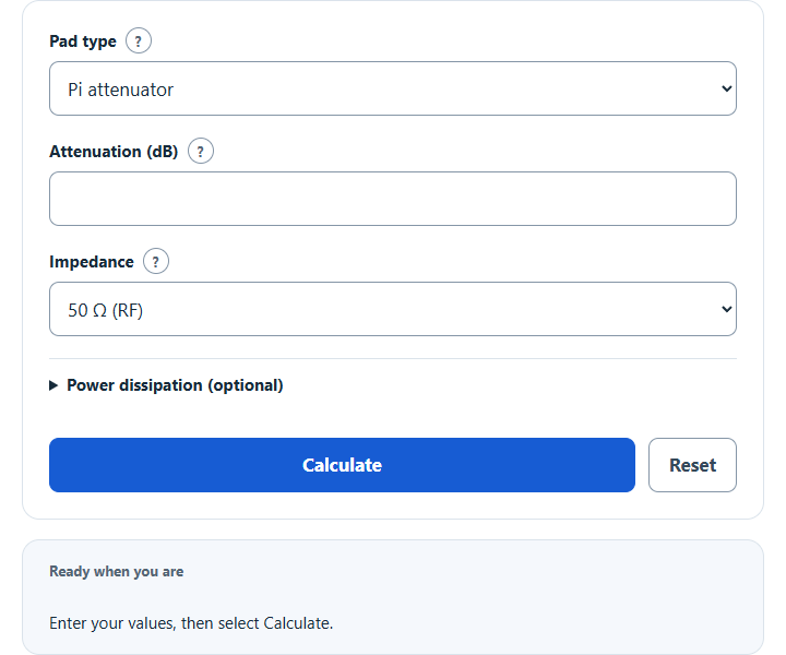
Calculate the resistor values for a Pi or T attenuator pad from the attenuation in dB and the line impedance, with 50, 75 and 600 ohm presets.
- All Physics Calculators
- Attenuation Calculator
- Voltage Divider Calculator
- dB to Voltage Calculator
- Resistor Tolerance Calculator
- Impedance To Resistance Calculator
Calculator Functions
The calculator gives the resistor values for a symmetrical resistive attenuator pad that keeps the line matched: a chosen loss in dB with the same impedance at both ports. Select a function to open it in the calculator.
| Function | Use it when | You enter |
|---|---|---|
| Pi attenuator | You want one resistor in the signal line and a resistor to ground at each end | Attenuation in dB and the impedance |
| T attenuator | You want two resistors in the signal line and one to ground between them | Attenuation in dB and the impedance |
The impedance can be 50 Ω for RF, 75 Ω for video and cable TV, 600 Ω for audio lines or a custom value. Both pads give the same attenuation and match, and use three resistors each [1]. Enter the input power in the optional section to see how much each resistor dissipates. To measure the loss of an existing circuit in dB, use the Attenuation Calculator.
Attenuator Formulas
| K | Voltage ratio, input voltage divided by output voltage |
| A | Attenuation (dB) |
| Z | Impedance of the source and the load (Ω) |
Both pads are worked out from K and Z. A 6 dB pad has K = 1.9953, so it halves the voltage and passes about a quarter of the power.
Pi attenuator
The Pi pad has one series resistor Rs in the signal line and two equal shunt resistors Rp, one from the input to ground and one from the output to ground. For 6 dB at 50 Ω the shunt resistors are 150.48 Ω and the series resistor is 37.35 Ω.
T attenuator
The T pad has two equal series resistors Rs in the signal line and one shunt resistor Rp from their junction to ground. For 6 dB at 50 Ω the series resistors are 16.61 Ω and the shunt resistor is 66.93 Ω.
Power dissipation
The load receives Pin ÷ K² and the pad turns the rest into heat. The calculator splits that heat between the three resistors from the voltage across each one, or the current through it, with the pad driven and loaded by Z. The resistor nearest the input always takes the largest share, so rate it with a margin.
Limits of This Estimate
- The formulas are for equal source and load impedance. A pad that also changes impedance, such as 50 Ω to 75 Ω, needs different values.
- The values are exact, and real resistors come in standard steps. Rounding to the nearest standard value shifts the attenuation and the match slightly; 1% parts keep both close.
- Keep a single pad to about 20 dB. At higher attenuation, stray capacitance, inductance and grounding let signal leak around the pad, so build a larger loss from two or more pads in a row [1].
- At radio frequencies use non-inductive resistors, such as surface-mount parts, and check their power rating [1]. The dissipation figures assume a matched source and load.
Sources
- Electronics Notes, Pi and T Resistive Attenuator Pads: RF Circuit Design: Pi and T pad resistor formulas, the 20 dB per section guideline and resistor choice