Calculate ideal PWM duty cycle, on-time, frequency or power ratio. Optional power and voltage give average power and average/RMS voltage for zero-low rectangular pulses. Injector mode uses RPM and one pulse per four-stroke cycle.
- All Physics Calculators
- Injector Duty Cycle Calculator
- Natural Frequency Calculator
- PWM to Voltage Calculator
- RF Average Power to Peak Power Calculator
- Hz to Period Calculator
Duty Cycle Formula
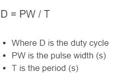
For repeating rectangular pulses, D = on-time × frequency = on-time / period; duty (%) = 100D. On-time = D / frequency, period = 1 / frequency and off-time = period × (1 − D). Frequency from D / on-time requires both to be positive. In the ideal zero-off-state power model, D = average power / on-state power. Optional average voltage is Von × D and RMS voltage is Von × √D. See Texas Instruments’ PWM reference design. Switching losses and load dynamics are outside this arithmetic.
Injector Mode Formula
Injector duty cycle shows how much of the available injection window an injector is commanded open. For a 4-stroke engine with one injection event per engine cycle, the calculator uses:
An equivalent simplified form is:
The available time for one complete 4-stroke engine cycle decreases as RPM increases, which is why duty cycle rises quickly at higher engine speeds:
| Variable | Meaning | Typical Units | Notes |
|---|---|---|---|
| IDC | Injector duty cycle | % | Percent of available injector on-time being used |
| RPM | Engine speed | rev/min | Higher RPM reduces the time available per cycle |
| IPW | Injector pulse width | ms | How long the injector is commanded open for each event |
| tcycle | Cycle time | ms | Total time for one 4-stroke engine cycle |
What the Calculator Tells You
This result helps you evaluate whether an injector still has operating headroom. As duty cycle increases, the injector spends more of each cycle open and has less margin left for additional fuel demand. A value approaching 100% means the injector is nearly open continuously, leaving very little control range.
How to Use the Calculator
- Choose Injector duty from RPM and pulse width, then enter engine speed in RPM.
- Enter injector pulse width in milliseconds.
- Calculate the duty cycle percentage.
- Compare the result against your tuning target to see whether injector capacity is becoming a limitation.
Example
If the engine is running at 6000 RPM and injector pulse width is 12 ms, then:
That means the injector is open for 60% of the available injection window.
Why RPM Matters So Much
At low RPM, the injector has a relatively large amount of time available each cycle. At high RPM, that window becomes much shorter, so even the same pulse width represents a larger percentage of the cycle.
| RPM | Available Time per 4-Stroke Cycle | Effect on Duty Cycle |
|---|---|---|
| 1000 | 120 ms | Large injection window |
| 2000 | 60 ms | Duty cycle rises faster |
| 4000 | 30 ms | Less headroom available |
| 6000 | 20 ms | Injector time becomes more limited |
| 8000 | 15 ms | Very small operating window |
General Interpretation Guide
| Duty Cycle Range | General Meaning |
|---|---|
| Below 50% | More than half of the assumed cycle remains off; this alone does not verify adequate fuel delivery |
| 50% to 75% | 25% to 50% of the assumed cycle remains off; check actual manufacturer and ECU limits |
| 75% to 90% | 10% to 25% of the assumed cycle remains off; actual operating margin depends on the system |
| Above 90% | Less than 10% of the assumed cycle remains off; duty alone cannot certify suitability |
Rearranged Forms
If you know the target duty cycle and want to solve for a different variable, these forms are useful:
Important Assumptions
- The formula assumes a 4-stroke engine.
- It assumes one injector pulse every two crankshaft revolutions.
- Pulse width must be entered in milliseconds unless the calculator input is switched to seconds.
- This simplified calculation does not account for injector dead time, battery-voltage effects, staged injection, or unusual ECU firing strategies.
Common Reasons for High Duty Cycle
- Injector size is too small for the airflow and fuel demand.
- Engine RPM has increased while pulse width remains large.
- Fuel system pressure or injector performance is not meeting target conditions.
- The tune is commanding richer mixtures under boost or heavy load.
Common Input Mistakes
- Entering pulse width in seconds when the value is actually in milliseconds.
- Using the wrong engine operating point for RPM or pulse width.
- Assuming a high duty cycle always means a bad injector; sometimes it simply reflects system sizing.
- Applying this exact formula to engines or injection strategies that do not match the one-pulse-per-cycle assumption.
Injector mode estimates commanded open-time fraction under the stated one-pulse-per-four-stroke-cycle assumption. It does not certify fuel-system headroom. Holley’s EFI manual defines injector duty in relation to opening time and cycle time; ECU reporting and pulse strategies can differ.