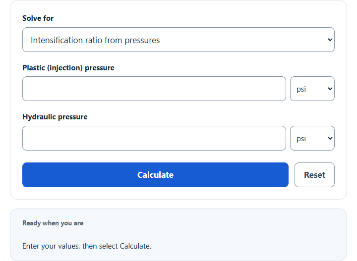
Calculate intensification ratio from plastic and hydraulic pressures or piston and screw diameters, and convert pressures between machines.
- All Physics Calculators
- Injection Molding Cooling Time Calculator
- Injector Duty Cycle Calculator
- Formation Pressure Calculator
- Injection Pressure Calculator
Calculator Functions
| Function | What it does | What it requires |
|---|---|---|
| Intensification ratio from pressures | Finds the ratio of an injection molding machine from one pair of pressures | Requires the plastic (injection) pressure and the hydraulic pressure that produces it |
| Plastic pressure | Converts a hydraulic gauge reading to pressure on the melt | Requires the hydraulic pressure and the intensification ratio |
| Hydraulic pressure | Finds the hydraulic setting that gives a wanted plastic pressure | Requires the plastic pressure and the intensification ratio |
| Intensification ratio from diameters | Finds the ratio from the machine’s geometry | Requires the hydraulic piston diameter and the screw diameter |
| Machine 2 hydraulic pressure | Finds the hydraulic setting on a second machine that matches the plastic pressure of the first | Requires the Machine 1 hydraulic pressure and the ratios of both machines |
| Machine 1 hydraulic pressure | Finds the hydraulic setting on the first machine that matches the plastic pressure of the second | Requires the Machine 2 hydraulic pressure and the ratios of both machines |
Pressures can be entered and shown in psi, bar, kPa or MPa, and diameters in mm or inches. The intensification ratio field starts at 10 and should be replaced with the figure from the machine’s specification when it is known.
Intensification Ratio Formulas
| IR | Intensification ratio, written as a number to 1 |
| Pp | Plastic pressure: the pressure on the melt in front of the screw |
| Ph | Hydraulic pressure: the oil pressure in the injection piston, in the same unit |
Intensification ratio from pressures
A machine that puts 20,000 psi on the plastic at 2,000 psi of hydraulic pressure has a ratio of 20,000 ÷ 2,000 = 10:1, and 25,000 psi at the same hydraulic pressure is 12.5:1. A typical machine is about 10:1, and most fall between 7:1 and 15:1 [1].
Plastic pressure
A gauge reading of 1,500 psi on a 10:1 machine means 1,500 × 10 = 15,000 psi on the melt, before any losses.
Hydraulic pressure
A process sheet that calls for 12,000 psi of plastic pressure needs 12,000 ÷ 10 = 1,200 psi of hydraulic pressure on a 10:1 machine.
Intensification ratio from diameters
The ratio is the hydraulic piston area divided by the screw area [1]. Both are circles, so the areas reduce to the piston diameter Dp over the screw diameter Ds, squared. A 120 mm piston driving a 40 mm screw gives (120 ÷ 40)² = 9:1. Because the screw diameter is in the formula, fitting a different screw to the same machine changes its ratio.
Machine 2 hydraulic pressure
Moving a mold between machines keeps the plastic pressure the same, not the hydraulic setting. A process that runs at 1,200 psi on a 10:1 machine puts 12,000 psi on the plastic. A 12:1 machine reaches that at 1,200 × 10 ÷ 12 = 1,000 psi. The result also lists the matched plastic pressure.
Machine 1 hydraulic pressure
This is the same transfer in the other direction. A setting of 1,000 psi on the 12:1 machine corresponds to 1,000 × 12 ÷ 10 = 1,200 psi on the 10:1 machine.
Limits of This Estimate
- The conversion is ideal and neglects losses [1]. Pressure drops through the nozzle, runner and cavity are not included, so pressure inside the mold is lower than the plastic pressure shown.
- The diameters function assumes one full circular piston. Machines with several cylinders or a ring-shaped piston area need the ratio from the manual, which often gives a separate curve for each screw diameter [1].
- The starting ratio of 10 is a common value, not a property of any particular machine. A result does not show that a machine can safely reach a pressure.
Sources
- Autodesk, Moldflow Insight 2015 Help, Calculating the machine intensification ratio: definition, typical value and range, the piston and screw area formula, and injection pressure from hydraulic pressure