Estimate theoretical injection-molding cooling time from wall and thermal data, reverse-solve thickness, and see cycle throughput plus quadratic sensitivity.
- All Miscellaneous Calculators
- Newton’s Law of Cooling Calculator
- Injection Pressure Calculator
- Melt Flow Index Calculator
- Melt Flow Rate Calculator
- Mold Shrinkage Calculator
- Plastic Shrinkage Calculator
Injection Molding Cooling Time Formula
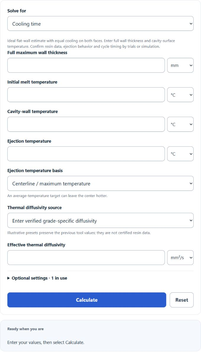
The calculator uses a first-term, one-dimensional plate-cooling model with full wall thickness and equal cooling on both faces. The default criterion is centerline (maximum) ejection temperature; the optional average criterion uses 8/pi² instead of 4/pi and can leave the center hotter. Thickness and thermal diffusivity must use consistent units. Temperatures are normalized to °C.
- tc = estimated cooling time, in seconds
- s = full wall thickness, in millimeters
- ln = natural logarithm
- pi = 3.14159
- Tm = melt temperature, in °C
- Tw = mold wall or mold temperature, in °C
- Te = ejection temperature, in °C
- alpha = thermal diffusivity of the plastic, in mm²/s
Enter a verified effective diffusivity for the resin grade and process, in mm²/s or m²/s. The four retained presets are illustrative values from the previous tool, not universal material properties. The thickness unit selector converts inches to millimeters using 1 in = 25.4 mm. Temperature controls convert the entered quantity when units change.
The temperature inputs must satisfy Tm > Te > Tw. Tw is the cavity-surface temperature, not automatically the coolant temperature. This first-term model is used only where the Fourier number based on half-thickness is at least 0.2; early-time targets require a fuller transient model. See the BASF cooling-time model and assumptions.
Illustrative Thermal Diffusivity Presets
These illustrative values match the retained presets. Effective diffusivity depends on grade, fillers, temperature and process conditions; use supplier or trial-calibrated data for process decisions.
| Illustrative preset | Effective diffusivity | Use |
|---|---|---|
| PP | 0.10 mm²/s | Illustrative only; replace with verified grade-specific data |
| PE | 0.14 mm²/s | Illustrative only; replace with verified grade-specific data |
| ABS | 0.09 mm²/s | Illustrative only; replace with verified grade-specific data |
| PC | 0.12 mm²/s | Illustrative only; replace with verified grade-specific data |
Input Rules and Result Sensitivity
| Input or condition | Effect on cooling time |
|---|---|
| Wall thickness increases | Cooling time rises with thickness squared. Doubling wall thickness gives about 4 times the cooling time, if other inputs stay the same. |
| Thermal diffusivity increases | Cooling time decreases because heat moves through the material faster. |
| Ejection temperature is set lower | Cooling time usually increases because the part must cool further before ejection. |
| Mold temperature is raised | Cooling time can increase because the mold removes heat less aggressively. |
Example Problems
Example 1: ABS part in metric units
Suppose you have a 2.5 mm ABS wall, alpha = 0.11 mm²/s, melt temperature = 230 °C, mold temperature = 60 °C, and ejection temperature = 100 °C.
The estimated cooling time is about 9.72 seconds, or 0.1620 minutes.
Example 2: PP part using inches and °F
Suppose you have a 0.12 in PP wall, alpha = 0.14 mm²/s, melt temperature = 430 °F, mold temperature = 100 °F, and ejection temperature = 180 °F.
First, 0.12 in converts to 3.048 mm. The temperatures are converted to °C before calculation.
The estimated cooling time is about 11.15 seconds, or 0.1859 minutes.
FAQ
Why does wall thickness affect cooling time so much?
Cooling time is proportional to wall thickness squared. A small increase in wall thickness can make a large difference in cycle time. For example, increasing a wall from 2 mm to 4 mm does not double the estimated cooling time. It increases it by about 4 times, assuming the same material and temperatures.
What ejection temperature should you use?
Use the temperature where the part is rigid enough to eject without warping, sticking, or leaving ejector marks. This depends on the resin, part geometry, mold design, and acceptable dimensional change. The ejection temperature must be above the mold temperature and below the melt temperature for the formula to work.
Is this the same as total cycle time?
Cooling time is one part of the cycle. Add only nonoverlapping time outside this cooling interval; packing and recovery may overlap cooling and must not be counted twice. Modeled part throughput also uses the entered parts per cycle and assumes continuous operation without rejects or downtime.