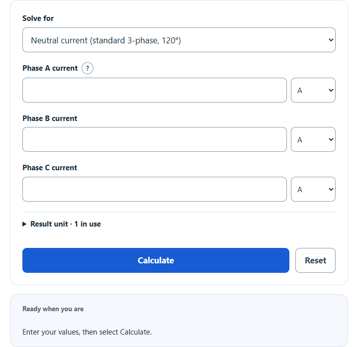
Calculate the neutral current in an unbalanced 3 phase system from the three phase currents, using the standard 120° formula or custom phase angles.
- All Physics Calculators
- All Electrical Calculators
- Average Current Calculator
- RMS Current Calculator
- Peak Current Calculator
Calculator Functions
| Function | What it does | What it requires |
|---|---|---|
| Neutral current (standard 3-phase, 120°) | Finds the RMS neutral current of a 3-phase, 4-wire wye system whose phase currents sit 120° apart | Requires the Phase A, Phase B and Phase C currents |
| Neutral current (custom phase angles) | Finds the RMS neutral current as the vector sum of three phase currents at any angles | Requires the Phase A, Phase B and Phase C currents and the current angle of each phase in degrees |
Each phase current is an RMS value in A, mA or kA, and all three are taken as measured at the same time. Every result also shows the largest phase current, the neutral current as a percentage of it, and the real and imaginary parts of the phase-current sum. The optional Result unit setting switches the output between amperes, milliamperes and kiloamperes.
Neutral Current Formulas
− AB − BC − CA)
| In | Neutral current (A, RMS) |
| A | Phase A current (A, RMS) |
| B | Phase B current (A, RMS) |
| C | Phase C current (A, RMS) |
The neutral of a 4-wire wye system carries the return of the three phase currents, so its current is their vector sum. With sinusoidal currents spaced 120° apart, the balanced portions cancel [1] and only the imbalance is left. Three equal currents give 0 A.
Neutral current (standard 3-phase, 120°)
The formula above applies directly. Phase currents of 10 A, 23 A and 3 A give √(100 + 529 + 9 − 230 − 69 − 30) = √309 = 17.58 A. The calculator evaluates the same expression in the equivalent form √[(A − B)² + (B − C)² + (C − A)²] ÷ √2, which stays accurate when the three currents are nearly equal.
Neutral current (custom phase angles)
+ C cos θC
+ C sin θC
θ is the angle of each phase current on a common reference, and the fields start at 0°, −120° and 120°. With those angles the result matches the standard function. Different angles describe loads whose power factors differ between phases: 10 A at 0°, 10 A at −90° and 10 A at 120° give X = 5, Y = −1.34 and a neutral current of 5.18 A, where the standard function would return 0 A. These are current angles, not the supply-voltage angles.
Limits of This Estimate
- The result covers the fundamental frequency only. Triplen harmonics (3rd, 9th, 15th) from single-phase non-linear loads such as computers and electronic lighting add in the neutral and do not cancel, and they can push neutral current as high as 173% of phase current even with balanced phases [1].
- The standard function assumes sinusoidal currents exactly 120° apart, which holds when every phase has the same power factor. Use the custom function when the power factors differ.
- The standard formula is the 120° case of the vector sum, worked out by algebra. These estimates are based on the best available data and estimations.
- This estimate alone cannot establish neutral conductor sizing, protection or code compliance.
Sources
- Mirus International, Triplen Harmonics (Wired IN, March/April 2007): balanced currents cancelling in the neutral, and triplen harmonics adding there