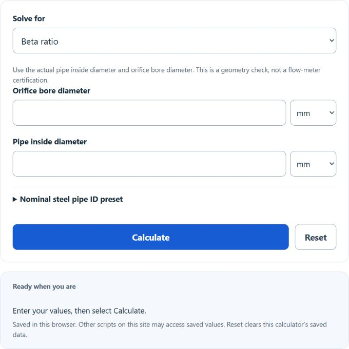
Calculate orifice beta ratio, or solve for orifice or pipe diameter from any two values, with unit options and NPS schedule pipe ID presets.
Related Calculators
- Hydraulic Horsepower Calculator
- Coanda Effect Calculator
- Pump Power Calculator
- Compressed Air Temperature Calculator
- All Physics Calculators
Calculator Functions
| Function | What it does | What it requires |
|---|---|---|
| Beta ratio | Finds the beta ratio of an orifice plate from its bore and the pipe it sits in | Requires the orifice bore diameter and the pipe inside diameter |
| Orifice diameter | Finds the orifice bore diameter that gives a chosen beta ratio in a known pipe | Requires the beta ratio and the pipe inside diameter |
| Pipe inside diameter | Finds the pipe inside diameter that gives a chosen beta ratio with a known bore | Requires the beta ratio and the orifice bore diameter |
Diameters can be entered in mm, cm, m, in or ft, and the two diameters do not need to share a unit. Beta ratio and Orifice diameter can fill in the pipe inside diameter from a nominal steel pipe size (NPS ½ to 12) in Schedule 40 or Schedule 80. A beta ratio below 0.10 or above 0.75 is calculated but shown with a warning.
Orifice Beta Ratio Formulas
| β | Beta ratio, a number with no unit |
| d | Orifice bore diameter |
| D | Pipe inside diameter, in the same unit as d |
Beta ratio
The bore diameter is divided by the pipe inside diameter after both are converted to meters. A 50 mm bore in a pipe with a 100 mm inside diameter gives β = 50 ÷ 100 = 0.5. The bore must be smaller than the pipe inside diameter, so a result of 1 or more is rejected.
Orifice diameter
A beta ratio of 0.6 in a 4 in Schedule 40 pipe, which has a nominal inside diameter of 4.026 in, needs a bore of 0.6 × 4.026 = 2.4156 in. The beta ratio entered must be greater than 0 and less than 1.
Pipe inside diameter
A 30 mm bore at a beta ratio of 0.4 corresponds to a pipe inside diameter of 30 ÷ 0.4 = 75 mm.
Beta ratio range for orifice meters
The API orifice metering standard for natural gas is based on beta ratios from 0.10 to 0.75, and the discharge coefficient is least uncertain between 0.2 and 0.6 with a bore of at least 0.45 in [2]. One meter manufacturer puts the coefficient uncertainty for flange taps at about ±0.5% between 0.2 and 0.7, and says it may be greater from 0.1 to 0.2 and from 0.7 to 0.75 [3]. The calculator’s warning uses the 0.10 to 0.75 range.
Limits of This Estimate
- The result is geometry only. A beta ratio inside the range does not show that a meter meets a standard, which also sets plate, tap and straight-pipe requirements.
- NPS is a trade size, not the inside diameter. The Schedule 40 and Schedule 80 presets are nominal steel pipe dimensions and do not allow for manufacturing tolerance, corrosion or lining, so a measured bore of the actual pipe is better. These estimates are based on the best available data and estimations.
- Schedule 40 and Schedule 80 are listed by schedule number. STD and XS wall thicknesses are not the same as those schedules at every pipe size.
Sources
- U.S. Bureau of Reclamation, Water Measurement Manual, Chapter 14, Section 3: beta as the ratio of orifice diameter to pipe diameter
- American Petroleum Institute, MPMS Chapter 14.3.2, Fifth Edition, summary sheet: the 0.10 to 0.75 range and the 0.2 to 0.6 range of least uncertainty
- Daniel, Fundamentals of Orifice Meter Measurement, Sections 6.6 and 9.1: beta ratio definition and uncertainty by beta ratio